This thread has been locked.

If you have a related question, please click the "Ask a related question" button in the top right corner. The newly created question will be automatically linked to this question.

TPS717-Q1: Output voltage stability

Part Number: TPS717-Q1

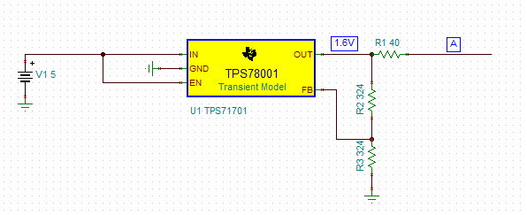
hi. The LDO output is set to 1.58V and operates as a strong pull up voltage, with 40Ohm resistor to point A

I have two questions:

  1. At some moment the voltage in point A might be 2V because of other device connected to this point. does the LOD is capable of sinking a current of 10mA? if not can I change the feedback resistor so the current will flow through them?
  2. When point A is disconnected  (no current is flowing) the output voltage is the same as the input voltage and stabilizes on the desired value only when the current is approximately 4mA

  • Hi Alexander,

    Unfortunately your picture doesn't seem to have come through but based on your description yes the problem is that LDOs do not sink current but yes if it works for your application you can increase the feedback resistors to act as a load and pull the output back down to where it should be.

    Can you reattach the picture so we can assess question #2. Also was the output already pulled high when A was disconnected? If so how long did you wait? it may simply take a little while to discharge the output caps through the resistor divider (depending on their current values). 

  • Hello Kyle

    Regarding question 1: the only option is to sink current through the feedback resistors?

    To clarify question 2. I have a dynamic load at point A that can be changed depending on the circuit state. when there is no current flowing through R1 the output of LDO is 5V and it drops to 1.6V only when approximately 4mA of current is going through R1 to a load at point A.

  • Hey Alexander,

    If you didn't want to change the resistor divider you could add a resistive load from Vout to GND to sink the the current. 

    If the output voltage is going to 5V when unloaded but then recovers when loaded with as little as 4mA that seems to imply that there is something else providing current to that node and causing the voltage to rise. 

    There are a couple of questions I have about the diagram you provided.

    1. Where is the output capacitor?
      1. LDOs require an output capacitor to regulate properly and it should be on the node labeled 1.6 (before R1). 
    2. Why do you have a 40 Ohm resistor between the LDO output and the load (point A)? 
      1. This will result in significantly more load regulation, since the LDO regulates the point labeled 1.6 not point A. 
    3. Lastly it is best practice to include an input cap to help keep the input supply well regulated. 

    Maybe you have #1 & #3 covered and you just created a quick schematic, but I just wanted to check just in case that is the cause of the issue. 

  • Hi Kyle

    yes, I have 1uF both input and output capacitor.

    I made some measurement on 3 different LDOs, when there is no load at all the output is rising to 2.8V, and a soon as I add a load tit drops to the expected output voltage 1.58V with feedback resistors as in the image 324K each

    the 40Ohm resistor acts as a strong Pull-up. Voltage drop on the 40ohm resistor is small, around 0.25V 

  • Hi Alexander,

    Based on the 40 Ohms and 0.25V drop across your "pull up" resistor, that means that you have current flowing into the node labeled on your plot as 1.6V and since LDOs are only intended to source current you will need to provide a resistor to ground in order to keep the LDO regulating. On the schematic I would recommend placing it after your output cap and before R1. 

  • Hi Kyle.

    I have added a resistor to sink reverse current. this is not the problem. the issue is as I described before:

    when the LDO has no load. It is pushing higher voltage than expected. 

  • Hi Alexander,

    Just to confirm, did adding the resistor to sink the reverse current eliminate the issue?

    This device is designed specifically to be stable with no load and this family of devices has been in the market since 2006 and has shipped hundreds of millions of units so it doesn't seem to be a systemic issue. That doesn't mean it's impossible to have a problem but if the device normally operated with the output going above the regulated set point with 0mA load it would have been reported, So if you want to continue debugging/evaluating the no load performance I'd recommend disconnecting R1 to isolate the LDO from the rest of the circuit just to 100% verify that there isn't a reverse current flowing. Maybe you've already disconnected that resistor but since I'm not there in your lab to see the many things you've tried I just want to verify.