This thread has been locked.

If you have a related question, please click the "Ask a related question" button in the top right corner. The newly created question will be automatically linked to this question.

BQ25120A: PCM lock

Part Number: BQ25120A

Hi,

I am having a similar problem as posted on other threads but I have not seen a solution for this IC. We have a design using BQ25120A which does not charge the batteries correctly when the PCM has detected overdischarge on the battery.

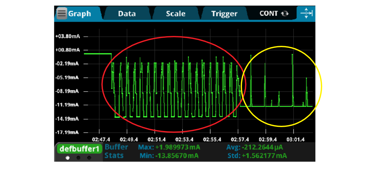
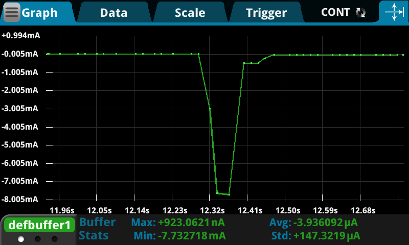
The batteries that we are using include a PCM that disables the discharge FET at around 3V. When this happens and we try to charge the battery we see a charging current of just 50uA and the voltage at the board VBAT is 1.95V. When the battery is not over-discharged the charging goes fine. 

Here is the schematic of the PCM and if you need to see our system's schematics I will be happy to send it to a company Email.

Thank you

  • Hello,

    What is the pre-charge current you set the charger to in your system?

  • Hi,

    Thank you for your prompt response.

    The resistors set the pre-charge current to 4mA.

    Regards.

  • If you change the pre-charge setting to 10mA, do you still see this behavior?

  • Hi,

    Yes, I changed the resistors to set a 10mA pre-charge current and still see this behavior.

    Regards

  • I have raised the precharge current to 20mA and it seems like around 3V we are able to unlock the PCM, but now I have observed a new issue. If the battery is under 2.9V, when we place it on the charger, the charge current goes up to 15mA and the voltage up to 3.5V, but after 550ms approximately, the voltage goes down to 1.9V and the current goes to 50uA, as you can see on the images below. Also, if the battery voltage is 2.9V, at charge it goes directly to 1.9V and 50uA. Any ideas what might cause this?

    Thank you

  • In the current design we power the system not through PMID but directly connecting the system regulators to the battery, and we use BQ25120A just to charge the battery. We suspect that this might have something to do with BQ shutting down the charge. We have modified the system, connecting all the regulators to PMID and there is a substantial behavior change. Now it looks like there is still something switching down the charging current as we saw on the original circuit, but it goes back on until there is enough voltage to turn on the system. In the image below you can se the current analysis at charging from the modified system. In red is the oscillating state as it looks like it is trying to turn on the system, and then in yellow the system is ON and functioning normally while charging the battery. Any ideas what might be switching off the charge at the first stage?

  • Hi ,

    It seems that we have been able to found the origin of the issue. There seems to be two different problems that combined produced this behavior. 

    One was that we set /CD pin high to communicate with the BQ at bootup, and that would have a major impact when the battery is depleted.

    The other factor is the PRETERM and ISET resistor.

    Removing the /CD setting and increasing PRETERM and ISET seems to solve the issue, but there is one question left that I would appreciate your help answering. As I mentioned before, we are not powering the system through PMID but directly connected to VBAT. If we modify the system so it is powered through PMID, we don't need to modify PRETERM and ISET, as the system is able to charge the depleted battery and reconnect through the PCM just fine if we remove the /CD setting. Could you help us figure out why does this happen? We are considering modifying our design so all the power goes through PMID but we want to be sure of the implications.

    Thank you for your help

  • Hello Husein,

    Sorry for the late reply. I was out of office for a few days.

    When VIN is present, you don't need to change /CD to communicate with the device. Setting /CD high with VIN present will disable charge which could've been causing an issue.

    Also your load should go through PMID not battery. You current implementation could have effect of pre-charge current, charge termination and charge times.

  • Hi ,

    Even though I said that we had solved the issue, this is only true on one of our products. We have tried to implement the same changes on other product ( increase ISET & IPRETERM resistors and remove /CD setting while charging) but this not solve the issue. We are evaluating redesigning the system so all the load goes through PMID but we need to find a solution for the already manufactured devices.

    As said, the system charges fine when the battery is not depleted, but when the battery is so low that the PCM disconnects the battery from the system, even with the suggested modifications we see that the system goes on and after an initial peak, it stops charging. Could you help us find a solution for this problem?

  • Hello,

    It seems the protector is causing issues. Do you see the battery voltage increase and then drop in voltage while charging?

  • This is the battery voltage at the board (after the PCM) when the charger is connected.  As you can see the voltage was 0V because the PCM has disconnected the battery from the system. When the charger is connected it goes up and then after 140ma approx, it goes to 1.9V.

    The second figure is the current variation.

  • Hello Husein,

    I'll reach out to you directly on how to solve this.