A related question is a question created from another question. When the related question is created, it will be automatically linked to the original question.
If you have a related question, please click the "Ask a related question" button in the top right corner. The newly created question will be automatically linked to this question.
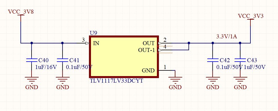
Please see figure 4 and figure 5 in the datasheet regarding dropout voltage. You will want to make sure that you have enough headroom (3.8V - 3.3V = 0.5V of headroom) for your application's load current. The datasheet requires 1 uF minimum capacitance on the output to maintain stability, so please make sure that the tolerances on C42 and C43 will maintain 1uF minimum at all times.
1. Regarding the drop out voltage, our application requires max current of 0.8A So as per the figure 5 at 0.8A load current @85C, Vdrop is 380mV,
2. and for Input voltage v/s V drop referring to Figure 4, Yes as you said Vdrop is 0.5V @ Vin 5V and @ 85C. So, In my circuit also 3.8-3.3=0.5V, So is this fine?What do you think.
3. Output capacitor: In the design I have given 2 Capacitor 0.1uF and 1uF. I didn't understand the sentence you mentioned"please make sure that the tolerances on C42 and C43 will maintain 1uF minimum at all times" please.
4. When placing the multiple decoupling capacitors near the input and output pins of an IC, smaller vale capacitor should be placed near the supply pins first or larger value Cap placed near the supply pins?
1 and 2) It looks like you have enough Vdrop for your application.
3) The output capacitors are ceramic capacitors. Ceramic capacitors have tolerances in the +/- 10% to +/- 20% range, and they are also susceptible to bias voltage where the closer you get to the rated voltage the less capacitance you will actually have in the application. The capacitors you have chosen have plenty of margin at 50V rated with only 3.3V applied, so you are likely seeing a low percentage of capacitance loss here. Still, I would recommend placing two 1uF capacitors in parallel instead of 1uF // 0.1uF. The two capacitors in parallel will ensure that tolerance on the capacitors does not push them below the 1uF requirement for stability.
4) Smaller values should be placed near the input and output of the LDO. Larger values will be next.
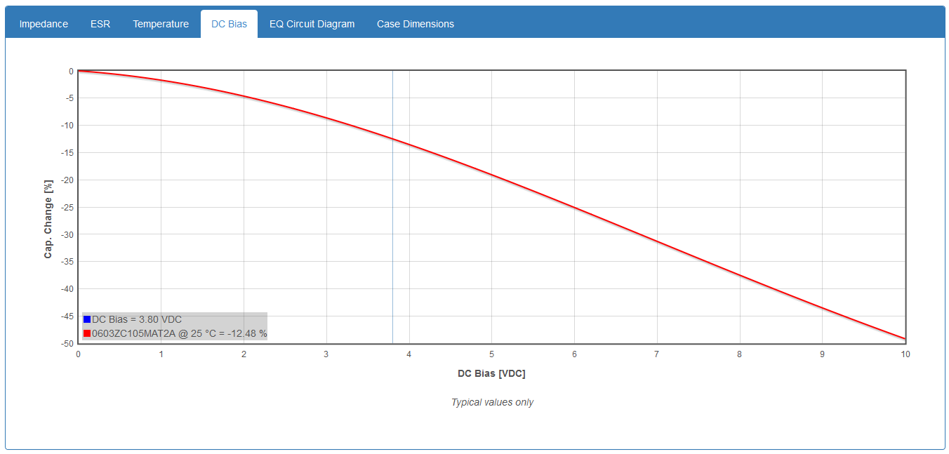
Based on your max voltage level of 3.8V and a 10V rated capacitor, you should be fine with 2x in parallel. Data from an example AVX capacitor suggests a loss of just 12.5% at this voltage bias level. Combined with 20% tolerance and you will still have plenty of margin to meet the 1uF requirement for stability.