This thread has been locked.

If you have a related question, please click the "Ask a related question" button in the top right corner. The newly created question will be automatically linked to this question.

LM3478: Doesn't get the efficiency during the higher current operation

Part Number: LM3478
Other Parts Discussed in Thread: CSD17309Q3, TPS61288

Hello Team,

I am using the LM3478 in our design from last 2 revision.

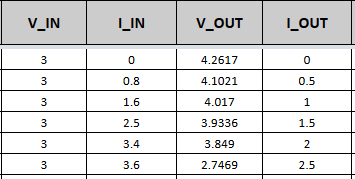
We are unable to get the efficiency during the high current application.

Vin - 3 to 4.2V (Lithium-Ion Battery 1S10P Config with 3C cells)

Vout- 4.2

Max Iout Current Application - 5.8A

Max Iout desinged for - 9A

I am unable to get the efficiency claimed in the Web-bench application graph.

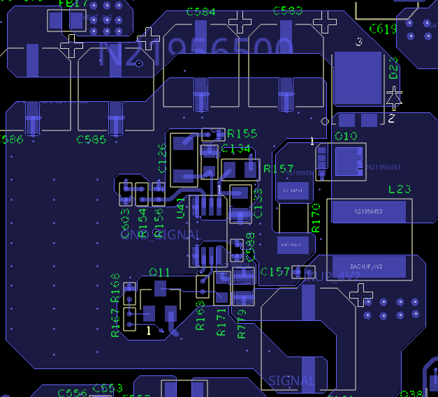
Below is the selected part list in the design.

Mosfet - CSD17309Q3

Diode - TSP10H45S S1G

Inductor - XAL7070-102MEC

Here i am also attached the efficiency test results, origional web-bench & our actual design schematic.

Let us know your suitable suggestion.

6663.Data.zip

  • Hi Pratik,

    Thank you for designing with the LM3478.  Note that the Webench model is based on the EVM.  Not sure if you followed the layout, which may cause additional losses if the PCB is not designed properly.  Could  you use a thermal camera to identify which component is the hottest on your board? 

    Honestly, regarding your 9A output,  you should consider a synchronous boost because the output diode can cause huge power dissipations, and it can become a major thermal issue unless you have a good heatsink. If the diode drop is 0.7V at 9A output, then the conduction losses of the diode will be 6.3W, which alone causes about 14.3% efficiency drop, not to mention the losses in the MOSFETs, and other components.  A synchronous boost converter like seems to be a better choice.  You may take a look of TPS61288.

    Thanks,

    Youhao Xi, Applications Engineering

  • Hello Youhao,

    Youhao: Not sure if you followed the layout, which may cause additional losses if the PCB is not designed properly. 

    Pratik: Kindly find the attached the screenshot for the layout.

    Youhao: Could  you use a thermal camera to identify which component is the hottest on your board?

    Pratik: We dont have any thermal camera, but using the IR thermometer will measure the temperature of highest compoenent and update you.

    Youhao: regarding your 9A output,  you should consider a synchronous boost because the output diode can cause huge power dissipations, and it can become a major thermal issue unless you have a good heatsink.

    Pratik: Let us know where to provide the heatsink.

    Youhao: If the diode drop is 0.7V at 9A output, then the conduction losses of the diode will be 6.3W, which alone causes about 14.3% efficiency drop, not to mention the losses in the MOSFETs, and other components.

    Pratik: Diode drop is 0.5V at 5.5A than total loss is around 2.75W. If we use lower drop voltage for Diode than we can increase the efficiency up to some instance. Mosfet drop is around 0.2V for 5.5A. Kindly correct my understanding.

    Youhao: A synchronous boost converter like seems to be a better choice.  You may take a look of TPS61288.

    Pratik: As per your suggestion, TPS61288 is in preview stage will not able to use in our design. Can you provide the test data for TPS61288 as per the our application. What is plan for TPS61288 for the production stage.

    Kindly provide the valuable suggestion how i can improve the efficiency in my current design by changing the some of components.

  • Hi Pratik,

    You layout can be improved.  The current sense resistor R170 should be rotated by 180 degree such that the ac current loop is direct, straight forward, and has the minimal spatial area enclosed.  The ac current loop include:  Q10-->R170-->Ceramic output capacitors-->D23-->Q10.   On your layout, this ac current loop unnecessarily runs a long distance on PCB.  I do not see ceramic capacitors but just see four electrolytic capacitors lined on and extended to the left. 

    However, I think the diode may cause the major losses.  The MOSFET is another piece of devices that you may pay attention too. 

    Regarding the TPS61288, I will need to contact our experts supporting it to comment.

    Thanks,

    Youhao

  • Hi Pratik,

    the TPS61288 is released by the end of this year. 

    the 9A output current is used by one loading or several loading?

  • Hello Youhao,

    We have tested the some scenarios and wants to know that why output voltage is decreasing linearly once load current started increasing.

    Looks like boost converter is not working as it should be.

    Let me know what is wrong here.

  • Hi Pratik,

    It seems something is affecting the duty cycle.  I revisited your attached Webench schematic in your first post, and found Cflt at the current sense pin (ISENSE) is only 10pF.  Could you raise it to 100pF and see if you maintain the output regulations?   

    Thanks,

    Youhao