This thread has been locked.

If you have a related question, please click the "Ask a related question" button in the top right corner. The newly created question will be automatically linked to this question.

LMR16006: Startup Problems

Part Number: LMR16006

We are utilizing the LMR16006Y in a design to regulate a supply from 20-44V down to 15V.

Application load current is 118mA.  Output capacitance is 41uF. 

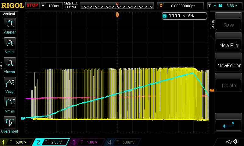
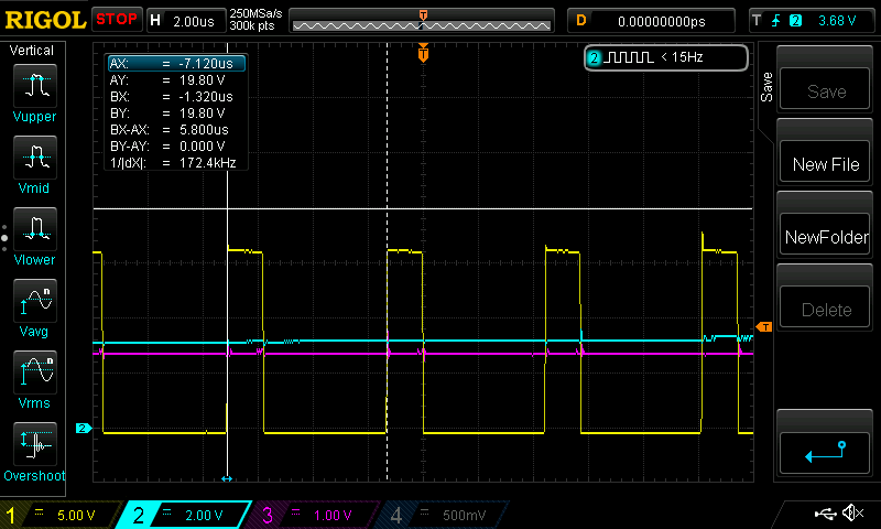
When power is first applied, the regulator switches at 172kHz-500kHz instead of 2100kHz.  In addition, the output reaches steady state at approximately 3.16V instead of the designed 15V. 

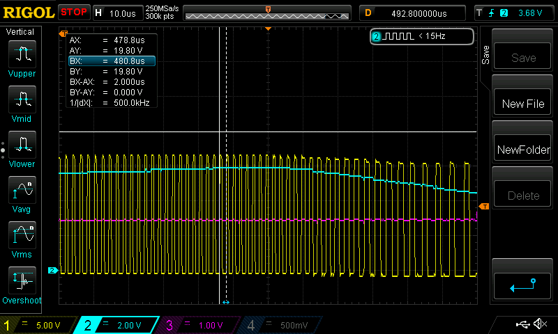
Rapidly cycling power to the regulator results in proper operation (2100kHz switching with ~14.9Vrms output).

The issue returns after removing power for ~20 seconds prior to re-applying power. 

Attached are scope captures for the regulator turning on.  For the following two images channel 1 is Vin (24V SLA Battery), channel 2 is the output voltage, and channel 3 is the SHDNn pin. 

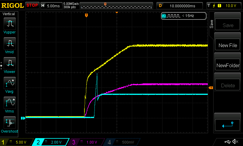
For the following three images channel 1 is SW pin, channel 2 is the output voltage, and channel 3 is the SHDNn pin. 

Is our input supply ramping too slowly for the LMR16006 to turn on correctly?

Are there suggestions on where to look to resolve this?

Thank you.

Please note: adding hardware to forcibly power cycle the regulator during boot is a band-aid solution that we will only pursue as a last resort.

  • Hello Timothy,

    Can you please share your schematic and layout for this?

    Thanks,

    Harrison Overturf

  • Hello Harrison,

    Here is our schematic

    Note: not shown in the schematic is a 10k resistor in parallel with C14.  This component was present in the scope captures posted earlier and was added to keep the regulator off until the PVDD supply was >= 15V.  The issue persists when the 10k resistor is not present. 

    Top Layer:

    Layer 2

    Layer 3

    Bottom Layer

  • My apologies, it appears the images did not get uploaded. 

    Please see the images below:

    Thank you,

    -Tim

  • Hi Tim,

    Thank you for sharing the layout and schematic.

    I have a few tests that you can run to see if the performance improves:

    • Run the same tests without the C14 capacitor
    • Do you have another device/ another board to run the test on? Have you seen this same behavior happen across multiple devices?
    • Can you run the same test on an EVM? Do you see the same behavior on the EVM?

    Let me know if any of these tests show any improvements in performance.

    Regards,

    Harrison Overturf

  • Hello Harrison,

    We do not have an EVM to test with, however we do have other boards built up.  I have test two other boards which seem to avoid this issue, however, I think they are on the edge of not working. 

    Below is a scope capture of a different unit where channel 1 is Vin and channel 2 is Vout. 

    at the 2.3ms cursor in the image above the supply droops similar to the problem unit but instead makes a full recovery. 

    Removing C14 did not resolve the issue, however it gave us a clue on where to look next. 

    One element I neglected was that there is a linear regulator derived from the output of the LMR16006 and this linear regulator has ~160uF of capacitance on it.  Currently the linear regulator has a delayed turn on (implemented with a circuit identical to R12 and C14) which is causing the voltage droop in the image above.  Removing this delay such that the linear rises with the LMR16006 results in a successful power up. 

    Disabling the linear regulator during power up also allows for the LMR16006 to successfully power up, however, the regulator fails (similar behavior as initially reported) when the linear regulator is enabled. 

    This raises a couple other questions.

    What is the current limit during the regulator soft-start sequence? is it the 1.2A listed in table 7.5?

    Is the current limit (8.3.5 from the datasheet) a latching control? i.e. is a power cycle / reset required to clear it?

    Thank you,

    Kind Regards,

    -Tim

  • Hi Tim,

    To answer your questions:

    The current limit during the regulator soft-start sequence is the 1.2A typical and 1.7A maximum listed in table 7.5. This limit applies to normal steady state operation as well.

    The current limit is not a latching control, once the over load condition disappears, then normal operation should resume.

    Knowing about the linear regulator is useful, it sounds to me like this is definitely connected with the issue we are seeing.

    This brings me to my first question, does your system need the delay or would it be acceptable to remove the delay and let the linear regulator rise with the LMR16006?

    In the picture you posted above, was that taken with the linear regulator enabled?

    If so, when does the linear regulator get Enabled? Does it happen during that initial decrease in output voltage?

    Regards,

    Harrison Overturf

  • Hello Harrison,

    Yes, It is acceptable for us to remove the delay and allow both regulators to turn on simultaneously.

    Yes, In the picture above the linear regulator turns on during the power sequence.  Right when it turns on, the LMR16006 output droops to ~2.7V before both supplies ramp up together.

    After making the change such that both supplies turn on simultaneously, the droop does not occur.  Our plan is to perform this modification on all our boards as the solution moving forward.

    Thank you for your assistance.

    Kind Regards,

    -TIm

  • Tim,

    Glad to hear things are working smoothly now!

    Regards,

    Harrison Overturf