This thread has been locked.

If you have a related question, please click the "Ask a related question" button in the top right corner. The newly created question will be automatically linked to this question.

LM61440: Modifying feedback for dynamic current regulation

Part Number: LM61440

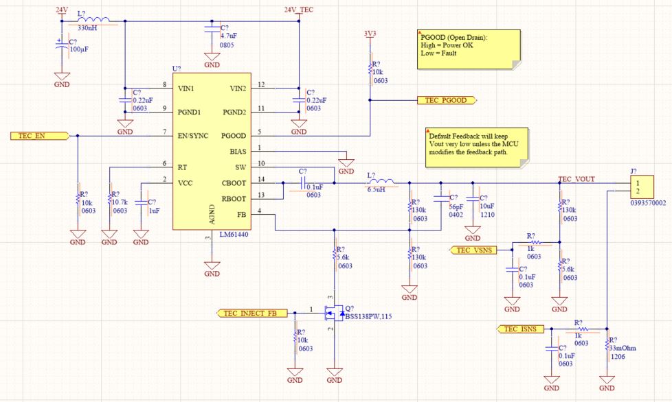
I'm planning on using an LM61440 as a dynamic current controlled source and am curious to hear any feedback on my approach to modifying the feedback path.
You'll see that I've made a very strong feedback path which will keep the output voltage very low in even if the MCU is checked out, but the MCU can control a NFET which modifies the feedback path and permits higher output voltages. My load is mostly resistive but will also be somewhat dynamic.

Some questions:
1. Should I attempt adding a filtering capacitor to the FB pin to remove any MCU PWM, or is this too much a risk of slowing down the loop response and stability?
2. Are there any other issues I should consider here in effectively interrupting the control loop of the LM61440 by inserting an MCU in the feedback path? I have injected an MCU into a regulator feedback path previously, but not with this specific component.

Looking forward to any feedback as long as it isn't "don't do this"!

  • Hi Jim

    For my understanding, when you mention dynamic current regulation, are you  referring to a constant current (CC) converter such that output current will remain constant regardless of changes in input voltage or output resistance? If that is the case, perhaps you can refer to this blog that talks about the external feedback network circuitry needed in order to converter the existing constant voltage (CV) buck converter into a CC/CV buck converter. 

    I have not tried injecting a MCU into the regulator feedback path before but I'd be concern with the control loop response if you were to input the PWM filter on the FB node. FB is sensitive to noise (so the PWM filter makes sense) but the filter might cause some instability in the system. I'd recommend getting hold of the LM61440EVM available on ti.com to test your application. This way you start off with a known good board that is optimized for proper regulation and can your desired external circuitry.  

    Regards,

    Jimmy 

  • Hi Jimmy,

    Thanks for your response!I do plan on using this device as a constant current regulator. The link you shared is great, though it is still designed for a fixed constant current target, whereas I plan on adjusting the current to close a separate temperature regulation control loop.

    The load is a thermoelectric element and really will not change very quickly. There are some characteristic changes with temperature, but the largest regulated changes will be my microcontroller commanding a target current change.

    It sounds like we share similar concerns with injecting a PWM signal into the feedback path, and I actually have an idea to break up the filter stage which might allow the default analog feedback loop to remain uninterrupted. I'll grab an EVM and try it out.

    Appreciate the help,

    Jim

  • Hi Jim,

    Thanks for the feedback and explanation on your application. It looks like you are all set with the next steps to test your circuit. 

    Because of this I will close this thread for now. In the case you have any device level questions on the LM61440, please feel free to reply back to this thread and it will reopen for further discussion.

    Thank you for using the E2E forum! 

    Regards,

    Jimmy