This thread has been locked.

If you have a related question, please click the "Ask a related question" button in the top right corner. The newly created question will be automatically linked to this question.

BQ24190: Battery pack stops charging after the battery has drained to 3.1V

Part Number: BQ24190
Other Parts Discussed in Thread: EV2400, BQSTUDIO

Hi,

We are using a combination of BQ24190 and BQ27531 in our battery packs and every so often we land into a scenario wherein BQ24190 does not charge the battery

On probing I found that when USB VBUS is connected and supplying 5V there is now current drawn and the voltage at the sw pins are 0V

CE is connected to GND

OTG= NC

Battery voltage =3.1V (3.6V lithium ion battery with a charging voltage of 4.2V)

ILIM = 422 ohms (~1.25A charging current)

I did try to read the status register of BQ27351 over BQ_Studio using EV2400 but was not able to register the device, all cells in BQ-Studio was greyed out

The only way I could recover the unit from this state was to disconnect all power (USB VBUS and Battery) and reconnect Battery after which I could see 3.4V on the SW pins and 0.3A at 5V at USB VBUS

What could have disabled BQ24190 SW pins preventing it from charging the battery. 

Thanks and Best Regards

Krishna

  • Krishna,

    Which power supports the I2C pull-up for the charger?

    Thanks,

    Ning.

  • Hello Ning,

    I2C lines of BQ24190 connect to BQ27531 and I2C line of BQ27531 are pulled up to 3.3V generated from SYS supply

    Since the sw outputs are off, I2C rails are floating.

    CE of BQ27531 is connected to SYS supply hence the system is in a lock-up state

    The big question for me is how did the sw outputs get disabled?

    Best Regards

    Krishna

  • Krishna,

    The key issue here is that when the device enters ship mode, the I2C pull-up goes away in the middle of I2C communication. If I2C pull-up stays high when the device enters ship mode, the issue can be solved. Please refer to https://e2e.ti.com/support/power-management/f/196/t/680331 for the detailes.

    Thanks,

    Ning.

  • Hello Ning,

    The Battery pack is in mission mode so its not expected to be in ship mode.

    I tried too recreate the scenario by disconnecting temperature sensor connection so the fuel gauge is reading  -41.35 deg C, I confirmed that charging current is 0mA (charging disabled at 0 deg C as per battery spec).

    Voltage at SW pins without USB_VBUS= 2.976

    Voltage at SW pins when USB_VBUS connected = 3.681

    Charging current as seen on BQSTUDIO = 0mA (I guess the BATFET is off at this stage)

    Overall I was not able to recreate the same issue wherein both BATFET and SW are all off

    Would you be able to let us know what conditions could set the device to

    1. Disable the SW pins even when we have USB_VBUS connected

    2. Disable BATFET

    Best Regards

    Krishna

  • Hello Ning,

    Not sure how sw pins on the BQ24190 could be disabled, I have tried to disable charging but that only turns the BATFET off similar to ship mode

    I have tried disable charging and put the unit into ship mode but it still does not disable sw pins, however there is no charging current voltage at battery is different from sys pin which confirms that BATFET is off

    would a multi master access on the I2C bus cause this kind of lockup?

    we have an MCU which should back-off from the I2C bus if its plugged into the unit at which time access to fuel gauge is dedicated for access to the main processor.

    I am not sure what could have disabled sw pins which prevents supply rail to be active even when +5V is applied at USB_VBUS.

    Thanks and Regards

    Krishna

  • Krishna,

    What are your test conditions such as VBUS (voltage at VBUS pin), IVBUS, VBAT (voltage at BAT pin), IBAT, VSYS, ISYS? Could you please provide the corresponding all register values of the charger?


    Thanks,

    Ning.

  • Hello Ning,

    Please find details below,

    VBUS= 5V (5V, 2A wall adapter)

    IVBUS = 0mA (no power is being drawn by the battery charger

    VBAT= 3.1V (3.6V, 5900mAh battery connected)

    IBAT = 0mA (no power is drawn from the battery

    VSYS = 0V

    ISYS = 0mA

    I was able to recover from the above condition only after disconnecting the battery and vbus (remove all power source) and re-connect battery.

    Please find the attached spreadsheet for register configuration, the attached spreadsheet is a register export of the battery pack in question after recovering the device from lockup (by disconnecting and reconnecting the battery)

    Thanks and Best Regards

    KrishnaBattery_Reg_19Nov2020.gg.csv

  • Krishna,

    When the battery drained to 3.1V, what was the VBUS pin voltage?

    Is there any battery protection circuitry in between BAT pin and the battery pack or does the battery have built-in battery protection?

    Thanks,

    Ning.

  • Hello Ning,

    Yes the The lithium-ion Battery has an internal protection circuit which has not in protection mode during the above issue.

    Typical Threshold for the protection circuit

    Over discharge: 2.3V

    Recommended Constant Operating Current: 3A

    Discharge Overcurrent: 4A

    Redundant Safety Fuse: 6A

    Best Regards

    Krishna

  • Krishna,

    Please check if the battery protection disconnects the battery from the BAT pin of the charger.

    Thanks,

    Ning.

  • Hello Ning,

    The battery protection circuit was not active during this scenario, the protection circuit was functioning normally.

    Could you please let me know if there is a mode which could turn either Q1 or Q2 OFF (Please find the attached snippet of Battery charger BQ24190 block diagram)

    Is there a test mode that could be set un expectedly that could cause Q1 or Q2 to be turned OFF?

    Would a signal on the OTG cause the device to malfunction?

    Observation:

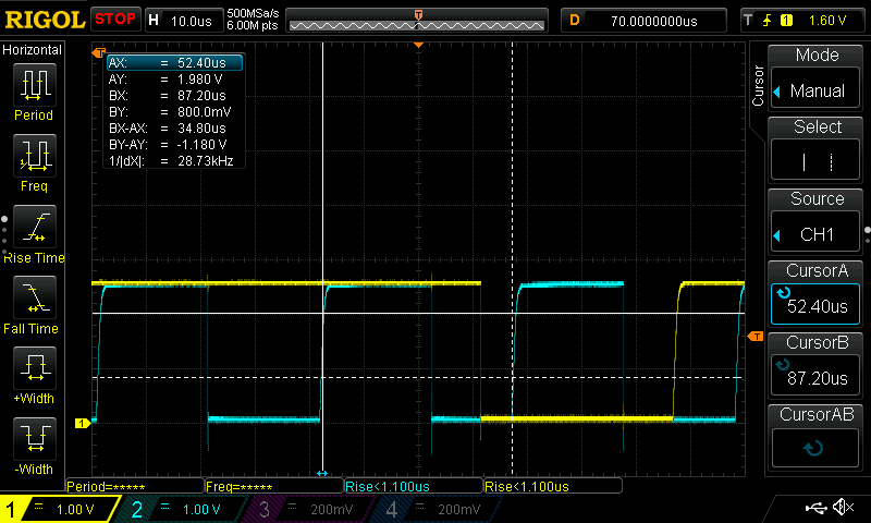
    The system side I2C interface for BQ27531 (Fuel Gauge) has two masters

    1. MCU operating and 100KHz

    2. SOM module operating at 400KHz

    The B side I2C interface between BQ27531 and BQ24190 was found to be operating at 28KHz is that expected.

    Please find the attached scope captures for the B-Side I2C interface between BQ27531 and BQ24190.

    Best Regards

    Krishna

  • Krishna,

    Q1 will be turned off in case of IRBFET_OCP (page 9 of the d/s) in boost mode.

    Q2 and Q3 are switching during normal operations.(fig 47-49 on the d/s)

    For easy debug, it is better to test the charger with the battery connected to the charger BAT and GND directly without any other circuitry.

    Please watch the video below for charger operations and valuable tips.

    Battery charger system overview (training.ti.com/battery-charger-system-overview

    Battery Charger Common Issues: Why my Battery is Not Charging (training.ti.com/battery-charger-common-issues-why-my-battery-not-charging

    Thanks,

    Ning.

    Thanks,

    Ning.

  • Hello Ning,

    We received another unit with exactly the same issue.

    I was able to take readings from all pins while the unit was in the failed state.

    Plugged the USB wall adapter to the unit

    USB_VBUS = 5.132V

    BAT+ = 3.193 (Battery is not in protection mode)

    SYS= 0.069V

    OTG= 0.001V

    PMID= 4.692V

    REGN = 0.000V

    ILIM=0.000V

    BTST=0.014VDC

    Later I soldered wires between SYS and GND and connected to a power supply 4.1V with current limited to 10mA

    as soon as I connected the SYS to power-supply the unit recovered from the issue and battery started charging.

    VBUS= 4.843V

    BAT+=3.498V

    SYS=3.52V

    OTG = 0.002V

    PMID=4.809V

    REGN=4.736V

    ILIM=0.967V

    BTST=8.14V


    What scenario could have disabled REGN? would a voltage limit on the Battery or charging battery temperature trigger disabling of REGN

    Note that this would have been when USB VBUS was not available (no USB connection)?

    Does this issue point us not connect CE pin of Battery Fuel Gauge of BQ27531 to SYS?

    Would it be better to connect CE pin of BQ27531 to BAT+ in-place of SYS?

    Best Regards

    Krishna Balekai

  • Krishna,

    1. Before USB_VBUS= 5.132V was applied, when only BAT+ = 3.193, what was SYS voltage?

    2. What circuitry does SYS voltage output support? Is SYS voltage used as I2C pull-up source?

    Thanks,

    Ning.

  • Hello Ning,

    Please refer to the the attached schematics from the post on 18th November2020.

    1. Before applying USB_VBUS when BAT+=3.193V, SYS=0.069V which stayed the same even after applying the USB VBUS = 5V

    2. SYS voltage is the main supply for the rest of the circuit, its also used for I2C pull-up resistors

    without SYS voltage the whole system is locked up and the only way we can recover is to dis-connect and re-connect the battery or apply external supply to SYS

    I suspect something disabled REGN which cascaded into SYS failure.

    What scenario could have disabled REGN? 

    Best Regards

    Krishna

  • Krishna,

    When when BAT+=3.193V (No VBUS), but SYS=0.069V, this means BATFET (Q4) is turned off. Please check if the host turns off Q4 via the BATFET_Disable bit (REG07[5]). Please refer to 9.3.1.2.1 BATFET Turn Off for the details.

    Thanks,

    Ning.