This thread has been locked.

If you have a related question, please click the "Ask a related question" button in the top right corner. The newly created question will be automatically linked to this question.

TPS55340: Adjustable output using PWM signal into FB pin

Part Number: TPS55340

Hello TI team,

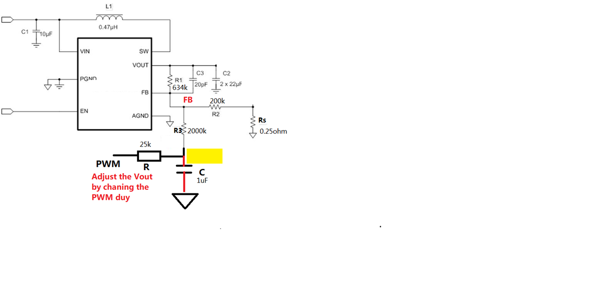
my customer wants to use TPS55340 as adjustable output, i want to suggest the schematic showed the link below;

https://e2e.ti.com/support/power-management/f/196/p/805795/2981984?tisearch=e2e-sitesearch&keymatch=tps55340%2525252520pwm#2981984

but i have some questions for this circuit.

1. what is the meaning of Rs(0.25ohm)?

2. I calculated Vout in this way, please check this is right or not.

  (1) i inserted PWM as 10KHz, 3.0V / 0V as high and low voltage and duty cycle of 75%. then after RC filter(25K, 1uF) I can get 2.25V

  (2) as resistor divider, i get FB voltage as 2.045V (ignoring Rs, 0.25ohm)

  (3) final Vout is, Vfb*((R1/R2)+1) = 2.045*((634/200)+1) = 8.528V

actually i am not sure what is the exact value of R2 in the schematic above.

please give me some advice to configure the final value, especially Rs and R2. Thanks.

Best regards,

Chase

  • Hi Chase,

    Thank you for posting.  To answer your questions:

    1.  It looks like a leftover when Helen copy from an existing circuit which uses Rs to sense a load current like in the LED lighting.  For your application, you do not need it and simply connect R2 to GND.

    2. In your design, the RC produced an average voltage from the PWM.  Called it Vc, the control voltage, then solve the following equations.  Assuming your PWM duty cycle range is 0% to 100%.  Then 

    Vc_min=0V

    Vc_max=Vhi_PWM

     [ (Vc_min / R) + (Vout_max /R1) ] / [ (1/R) +(1/R1) + (1/R2) ]  =VFB

    [ (Vc_max / R) + (Vout_min /R1) ] / [ (1/R) +(1/R1) + (1/R2) ]  =VFB

    Arbitrarily choose R2, say 10k, then you solve for R and R1.

    To choose C:  you need to make sure the RC can have good filter to minimize the ripple.  Select RC that its corner frequency is at least 100 below your PWM  frequency to obtain 40dB attenuation. 

    Thanks,

    Youhao Xi, Applications Engineering 

  • Dear Youhao,

    Thank you for your relpy.

    I have more question about this;

    1. is it okay to ignore R3? its value is 2000k.

    2. why do you use Vout_max in case of Vc_min? I think I should use Vout_max with Vc_max, and Vout_min with Vc_min.

    could you explain more about this equation?

    3. about RC filter, the frequency of PWM signal is 10KHz. then is it okay to set corner frequency to 9KHz? how about very low corner frequency like 10Hz? is it okay?

    Best regards,

    Chase

  • Hallo Chase,

    1. No, you should not ignore the value of this resistor. R3 should fullfil the following formula: R3 = R1 * (Vc-max - Vc-min) / (Vo_max - Vo_min)

    2. You are adding a control signal to the feedback node, so the higher this signal will be, the lower is the output voltage. Please have a look in this app note: 

    3. You need to choose the corner frequency above the frequency you want to change the output voltage with. Let's assume you want to change the output voltage every minute and the change shall happen in 1s, the corner frequency shall be higher than 1Hz. The corner frequency limits the rate of change you can achieve as it defines the minimum time the filter needs to change the voltage on R3.