This thread has been locked.

If you have a related question, please click the "Ask a related question" button in the top right corner. The newly created question will be automatically linked to this question.

TPS7A02: Transient response

Part Number: TPS7A02
Other Parts Discussed in Thread: TPS7A03, TPS783

Hello, 

I have a customer who is looking for ultra-low iq LDOs(under max 1uA),


4.3VBATT -> 3V output at 150mA max.


I offered the following devices which they liked:


TPS7A02              

TPS7A03

TPS783


Their main issue is the transient response,

They are asking if these devices can support 20mA at 1us transient, 150mA max current?

As this tag is extremely small, are there any capacitors that are recommended for this transient at smallest size possible?

Thanks, 

Victor Levy

  • Hi Victor,

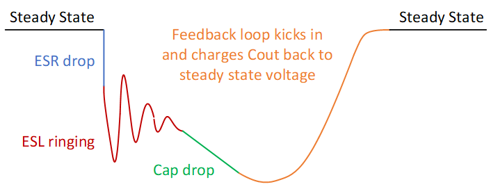
    Technically speaking, any LDO can support any load transient up to its full rated load current, it just depends on what output voltage variation is allowed in the application.  The TPS7A02 and TPS7A03 will perform better than the TPS783 which is an older device, based on the datasheet graphs and the math below. When the LDO output experiences a load transient, the feedback loop cannot react instantaneously so the initial droop will be due to the discharge of the capacitor.  This follows the simple capacitor equation I = C * dV/dt.  Before the droop there is inductive ringing (if there is too much inductance in the trace) and ESR drop (if there is too much resistance in the trace).  At the customers load current and step rate (20mA/1us) it is very unlikely that they will experience any issues with inductance or ESR, so we can focus on just the capacitance.

    From figure 11 in the TPS7A02 datasheet, we can extrapolate the time it takes for the feedback loop to kick in.  C = 1uF, dI = 50mA, dV = 165mV.  So dt = 3.3us.  A 20mA load step would therefore give an expected deviation of dV = 66mV. 

    From figure 16 in the TPS7A03 datasheet, we can do the same math to find dt = 2.5us.  A 20mA load step would therefore provide an expected deviation of dV = 50mV.

    From figure 17 in the TPS783 datasheet, the plot is too zoomed out to see the details but we can also estimate this as 20mA is 2x the load step that was used in the figure 17.  So we can estimate that the deviation is 2x as large, or about 220mV.

    If this deviation is unacceptable then you would simply increase the output capacitor until the droop meets the system requirements.

    Thanks,

    - Stephen

  • Great response!

    Thank you very much, 

    -Victor