This thread has been locked.

If you have a related question, please click the "Ask a related question" button in the top right corner. The newly created question will be automatically linked to this question.

TPS3700EVM-114: TPS3700 hysteresis

Part Number: TPS3700EVM-114
Other Parts Discussed in Thread: TPS3700, TPS61030, BQ24650

Hello,

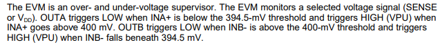
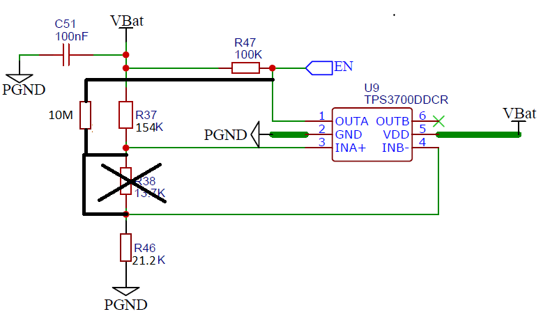
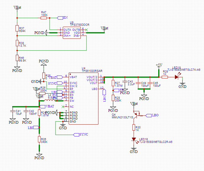
I was looking at the feasibility of adding a larger hysteresis to the suggested design found in the TPS3700EVM-114 with a gap of 0.1 V and how I would be able to do that with the schematic given below:

Schematic_New Project_2020-12-15_10-55-20.pdf

What should I change if I wanted to have my low voltage cutoff to be at 3.2 V and allow the ceiling of my hysteresis be at 3.3 V?? I have already taken a look at the guides posted by texas instruments online and I just was not sure how I would implement that in schematic above.

Thanks,

Abe


  • Hi Abe,

    See below.  The resistors will give you hysteresis for for INA+ and INB-.  You would need to size the resistors to give you the hysteresis you need.  Also, you can read up on "case 2" in the app note on how to add hysteresis to a voltage supervisor.:

    www.ti.com/.../slva360.pdf


  • Hello Ben,

    I've noticed that with the TPS3700 specifically, the VoutA value is floating and is limited once it passes the threshold. So if I'm using the VOUTA to run my 5V regulator's enable pin, while my battery input is >3.27 V the output of my regulator would be < 5V unless the battery's voltage exceeds 3.3V then my regulator outputs 5 V again. So between this 3.27 and 3.3 V my battery is struggling to charge properly as my loads begin to pull power. This causes my battery to fluctuate in the Vit- threshold.

    The whole purpose of the comparator was to prevent the load from pulling any power from my battery once it hits the low threshold and stays that way until it hits 3.3V. Once it does hit the 3.3V the enable pin should be set high and the output of the regulator does not go below 5 V. My regulator can go as low as 2.9 V and output 5 V as the datasheet suggests so I definitely think that the VOUTA connection to the enable is what's causing these issues.

    The comparator should cut off battery loads at 3.2 V and keep it this way until 3.3 V battery voltage where the regulator output voltage does not exceed 0 V. At  battery voltages above 3.3 V the regulator should go up to 5 V and not slowly ramp up to it as the charge in the battery increases. Am I correct to think that changing the hysteresis would solve this issue??

    Thanks,

    Abe   

  • Hi Abe,

    Yes, having hysteresis will help you avoid the voltage range between 3.27V and 3.3V.  Correct me if I am wrong but base on what you said above, you want the supervisor to output a "HIGH" when the battery voltage is above 3.3V.  Also, you want the output of the supervisor to stay high until the battery voltage is down to 3.2V.  Anything lower than 3.2V you want the supervisor to output a "LOW"  You can solve the resistor ratio you need to achieve your goal.  I believe we spoke about this in the other E2E thread.  Below is a pic to remind you the hysteresis that is built into the TPS3700:

    Ben

  • Hello Ben,

    It is true that with my current design the output is triggered "LOW" when <3.2 V and sets the enable pin of my converter to "LOW" setting the output voltage to 0 V. My concern is that as it is decreasing from 3.3V to 3.2V when draining the battery, the output voltage of my converter is limited to go less than 5V. For example, if my battery voltage is 3.28V, the output of my converter is not 5 V but it is 4.11V. 3.27 battery voltage gives 3.68 V at the output of the voltage regulator. At voltages < 3.25 V to be more specific gives 0 V at the output of my 5 V converter. This is not due to my regulator being faulty or anything of that sort, but it is due to the effect of the OUTA signal on my enable pin.

    The same happens when charging my battery from 3.2 V to the Vt+ threshold, there is a low output voltage at my 5 V converter at voltages between 3.2 V - 3.3 V as mentioned before and that would cause my loads to pull charge causing my battery to go below the Vt- threshold while charging. Since my charging source is via solar energy, the charging process is intermittent so the battery voltage would fluctuate up and down between my Vt+ and Vt- thresholds. The way I pictured the comparator would function is when OUTA is on logic "LOW", my converter would output 0 V and at logic "HIGH" would output 5 V.

    Would increasing the gap between the two hysteresis thresholds help overcoming this issue??      

    Thanks,

    Ibrahim

  • Also Ben, based on the documents you sent, I am confused as to what RH should be as I used the equations given in both cases 1 and 2 and I calculated RH as 36.67Mohm and 35.10Mohm respectively. 

    Here are the values I used for each variable in the calculation:

    R1: 604 kOhm 

    R2: 83.5 kOhm ( 69.8 + 13.7)kOhm

    Rp = 100 kOhm

    V1+ = 3.3 V

    V1- = 3.2 V

    Vs+ = 0.4 V

    Vs- = 0.3945 V

    V2 = 3.2 V

    Can you please verify whether my results are correct and will trigger my enable at the correct values??

    Thanks,

    Abe

  • Hi Abe,

    This is what I would try:

    R1 = 154K

    R2 = 21.2K

    Rp = 10M

    V+ = 3.31V (going up)

    V- = 3.21V (coming down)

    HYS = 100mV

    I hope this answers your question.

    Ben

  • Ben,

    I'm sorry but I am a bit confused. Why are you changing the resistor ratio from the one I already have?? Also what significance does increasing the Rp posses?? And I'm not sure what RH you are using if you are using a hysteresis resistor.

    Also the resistor combination chosen is consistent with the TPS3700-114 EVM module, I am testing combinations and making minimal changes to the neighboring resistors in the hope of finding one that works. Would it be possible for the future questions to make changes to the configuration on that board to better suit my design conditions??

    Thank you,

    Ibrahim 

  • Based on the schematic above, would I be able just to leave R38 and R46 as they are and swap out R37 with a 560 kOhm resistor and add a RH resistor of 1Mohm??

    The R37 value was calculated with equation (1) from the document you sent me and was found to be 560.648kOhm but the only resistors available to me from my supplier is 560 and 562 kOhm. I was also looking at keeping Rp as 100kOhm. I am trying to add the right 100mv hysteresis by altering the R1 value and adding a Rh resistor between INA+ and OUTA.

    Is that possible?? 

  • Hi Abe,

    I changed the resistor ratio that you had because the feedback resistor that is creating the hysteresis is quite large (>35Mohms).  For your application, you only need one resistor to create the hysteresis you need to meet your application goal.  Hopefully, these values will achieve your design goals.  See below.

  • Hi Abe, 

    Since your schematic does not use the output OUTB, you dont need to have R38.  You can remove R38 and place a 0ohm resistor in its place.  For R46, you will need to replace it with a resistor equivalent of something near 21.2Kohms.  R37 would need to be swapped out for a resistor value of 154Kohms.  The hysteresis resistor will be 10Mohms.  See the schematic that I have provided.  THis setup will give you the 100mV of hysteresis and meet your voltage thresholds (3.31V going up and 3.21V coming down).

    Ben

  • Hello Ben,

    Thank you for your detailed and technical help so far. I shall order the components from Digikey and make the changes soon. I shall update you on whether the issue is resolved or not.

    Best regards,

    Abe

  • Hi Abe,

    I really hope things will work out for you.  You can use a 10K and a 11.2K for in place of R38 and R46. 

    Keep me updated.  

    Ben

  • Hello Ben,

    I have made the changes and I've noticed that I'm still facing the same issues I had before in addition to it happening over a larger range. It seems that the comparator has no issue cutting off the voltage at voltages less than 3.2 V. The issue comes as the battery is being charged. I have also noticed that when I temporarily (for 10 seconds) trigger the LEDs at a battery voltage of 3.7 V while I am consistently drawing 1 A from my continuous load, the lights remain on and causes a voltage drop to 3.2V and remains this way (since the microcontroller unit needs at least 4.5 V to function and control the lights) till my battery capacity decreases to a value low enough to disable the converter.

    I'm confused as to whether my issues are stemming from my 5 V converter or comparator VOUTA pin as each works well individually just not together.

    Could there be something I am not taking into account?

    Thanks,

    Abe

  • Hi Abe,

    First off, are the new resistor values giving you the correct output signal from the TPS3700?  Is OUTA going high around 3.3V and going low around 3.2V?  

    Is the output of the TPS3700 goes to the EN input of the DC/DC converter?

    I am not sure about your application but it seems the TPS3700 is giving the correct hysteresis (100mV).

    Ben

  • Yes they are giving me correct values for OUTA at 3.3 V & 3.2 V. 

    Yes the output is connected to the EN input of the DC/Dc converter.

    The output voltage of the converter after the enable goes high is not what I expected as it is not strictly 5V and above. It rather gives 3.8 V and 4.2 V as its charging up until my battery voltage is charged up to a higher arbitrary value which gives 5V. This would not be an issue if the Enable is not connected to  my comparator

  • Hi Abe,

    Just curious, what is the voltage being applied to the converter?  Are you still using the same circuit as shown below?  I am curious, is that a 5V supply on the output of the converter?  What is the voltage of VBAT?  2.5V and 4.2V?  Is VBAT the same voltage being applied to the TPS3700?  How is VBAT generated?  Is VBAT = VBat??

  • Hello Ben,

    The voltage being applied to the converter varies between 2.5 V and 4.2 V depending on the state of charge of the battery. The comparator would however prevent the battery from being discharged lower than 3.2 V whether using the old voltage divider combination or the new one that possesses RH = 10M.

    I am no longer using the TSP61030 converter as it is giving me issues with its current limit constraints. So for the time being I am using pololu's U3V70F5 5 V converter module found here: 

    The +5V is not a voltage supply coming into the converter, it is just the net connection label for the output of the converter. VBAT is the same as VBat there is no difference between them and the battery voltage is for a 6000 mAh LiPo battery.

    I have posted the updated schematic below to better understand the load requirements of the system. Please note that the arduino MCU and HM-10 bluetooth are consistent loads and the WS2812B LEDs only trigger when the push button switch triggered and times out after 10 seconds. The main load comes from the USB output in the bottom right and is configured to supply charge to an iOS device.

    Schematic_Sunstation copy_2020-12-23_09-52-43.pdf

    Please let me know if further clarification or details are required.

    Thanks,

    Abe

  • Hi Abe,

    What is the EN spec for this converter module?  The only thing that I can say is that the EN signal that goes to the converter module is not a logic signal.  You mentioned earlier that when you apply a separate EN voltage to the converter module, the converter module's output works fine.  When the TPS3700 is used to output a signal to the converter module, the converter module does not output the right voltage, correct.  I feel we are almost there in figuring out your problem.

    Ben


  • Ben,

    According to the technical support I have reached out to in pololu, they replied with "For reference, a voltage below 0.4V on enable will disable the regulator and a voltage above 1.2V will enable the regulator." so I presume you are correct about the signal going into the converter not being a logic signal. Yes, when I output a signal from the TPS3700 is used to output a signal to trigger the enable pin of the regulator, the converter module does not output the full 5 V its capable of outputting. Instead, it outputs voltages of 3.8 - 4.4 V until the battery voltage is increased when it nears full charge, then it would supply 5 V.

    Also, I encountered the same problem when using the TPS61030 converter's enable pin. It would gradually increase the output voltage of the converter as the battery voltage is increased rather than just outputting a 5 V output once the battery passes the Vit+ threshold.

    Looking forward to hearing from you after the vacation,

    Abe

  • Hi Abe,

    Base on the information that you received from Pololu, any voltage above 1.2V on the EN of the regulator should be fine.  This means the voltage coming from TPS3700 should be high enough to turn on the regulator.  Is the output of the converter charging your battery?  

    Happy Holidays to you.

    Ben

  • Hello Ben,

    I apologize for the delay in replies due to the holidays. As per the schematic tagged above, the output of the converter is not connected to the battery. The sequence of the power signal originates from the solar panel source which is connected to the battery charger and buck converter circuit with the BQ24650 chip with its output connected to a hall effect current sensor which measures the current coming in and out of the battery. The battery is then led to the TPS3700's input pins which are also connected to the pololu boost converter and the output is connected to the loads of the system. The pololu converter's enable pin is controlled via the TPS3700's OUTA pin.

    Ill be happy to answer anymore questions to better understand the design.

    Thank you,

    Abe   

  • Hi Abe,

    At this time, the TPS3700 seems to be functioning properly within your system/application.  I don't have much understanding of the other parts of your application and I am not sure if I can be of more help.  If there are any other questions regarding the TPS3700, please let me know.  Thanks,

    Ben