This thread has been locked.

If you have a related question, please click the "Ask a related question" button in the top right corner. The newly created question will be automatically linked to this question.

BQ25505: VSTOR not needed - connect to VBAT_SEC ?

Part Number: BQ25505

Dear Support,

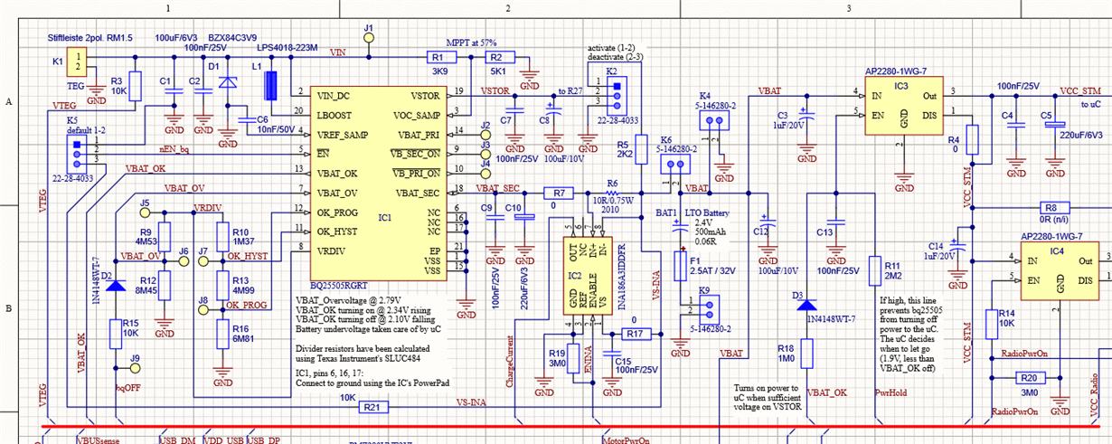
I'm using the bq25505 to charge a 2.4 V battery from a thermoelectric source. Initially, I had my circuit powered by the VSTOR pin but then I had to add charge current measurement (R6, IC2). The intention is to measure the full charge current, not the charge current minus some load current. So I removed all circuitry from VSTOR and connected it to the battery with switches. Now all current from the booster passes the current measurement on it's way to the battery. Refer to the above schematic.

With VSTOR not being used now, should I connect VSTOR to VBAT_SEC (R5 + K2) ? Should I isolate VSTOR ? Should I keep the capacitors (C7, C8) on VSTOR ?

I appreciate your help.

Best regards,
Martin

  • Hi Martin,

    You can connect VBAT_SEC to VSTOR.  You must leave the C7 decoupling capacitor and place it close to VSTOR and VSS pin.  C8 is no longer needed.

    Just curious about the small size of R1 and R2.  Those are loading the TEG.  Should they be larger valued?

    Regards,

    Jeff 

  • Hi Jeff,

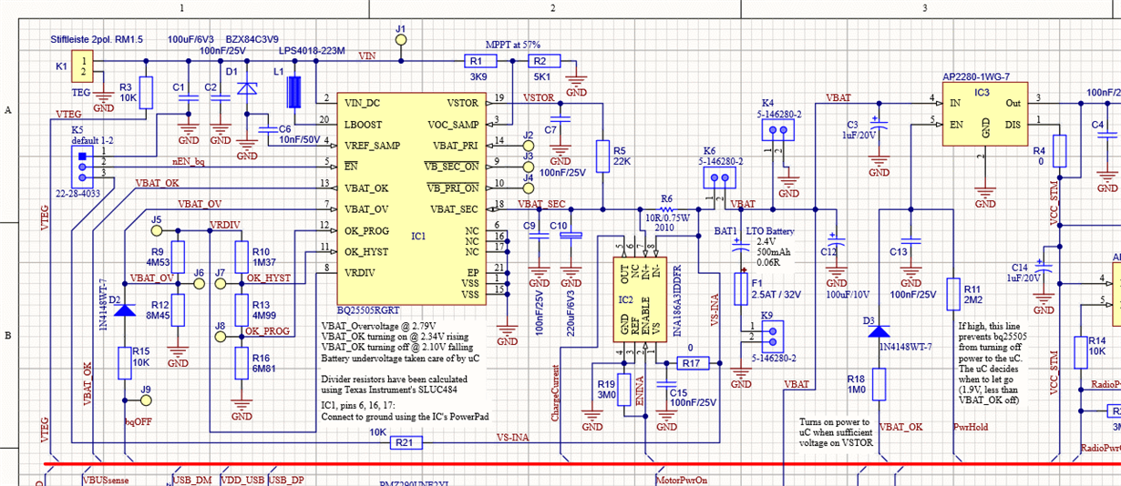
    1) I modified the schematic (above). C8 removed, R5 connects VSTOR and VBAT_SEC. Should I connect by 0 Ohm or is it safer to use several KOhm ?

    2) You mentioned that R1 and R2 are rather low in value and could load the TEG (connected at K1). Well, the TEG I'm using has a source impedance of < 5R, so the 9K of R1 and R2 are so much higher that they shouldn't have an effect. Confirmed by measurement. Am I missing something ?

    3) I have chosen a rather large capacity value for C1 (100uF vs the recommended 4.7uF), as in most situations, this results in a little extra current at the output. The 100uF are still small enough to not affect the MPPT. Does this make sense to you, am I missing something ?

    4) Divider resistors R9, R10, R12, R13, R16 are high impedance components, making the circuit sensitive to humidity and contamination. If I were to reduce the value of each resistor by a factor of 10, what impact would that have on the mean current ? (VRDIV is pulsed and most of the time it's off).

    Thank you for your help.

    Best regards,
    Martin

  • Hi Martin,

    Regarding 1, I recommend 0 ohm.

    Regarding 2, this charger is designed with very low Iq and can handle very low output power, hiZ sources.  It appears that your source isn't really HiZ.  On the flip slip, this charger's maximum avg input current is only about 100 mA.  If your TEG can provide more power than that, you might want to choose a higher power charger with VINDPM feature.  You can set VINDPM=MPP.

    Regarding 3, if your input source is lower impedance, then the 100uF should be okay. 

    Regarding 4, I recommend you reduce those resistors by at least a factor of 10 for the reason you site plus concerns about parasitic resistances created by solder flux.

    Regards,

    Jeff

  • Hi Jeff,

    1) 0 Ohm will not allow me shorting VSTOR to GND (because my battery is very low impedance).
    I do this (shorting to GND) occassionally for test purpose (enter cold start). Is it acceptable to use 100R ? Or at least 47R ?

    2) My thermoelectric generator delivers not even 40 mA at an open-circuit voltage of approx. 100 ... 300 mV.
    The bq25505 works nicely with it. I haven't found other chargers (outside the bq255-family) that perform well with such little input power. Did I miss something ?

    3) OK, this item closed

    4) If I reduce the resistors by a factor of 10, by how much does the average current drawn from VBAT_SEC increase ?

    Best regards,
    Martin

  • Hi Martin,

    Regarding 1, the internal PFET between VSTOR and VBAT_SEC has a body diode that is always present and allows current flow from VSTOR to VBAT_SEC.  When charging, adding the resistor in parallel with this diode speed up charge time until ICHG*R > Vdiode.  It appears that you want to use the undervoltage lockout that turns off the PFET in order to test cold start.  That should be okay.  Keep in mind that the PFET Rdson is close to 1ohm so if there is a load on VSTOR and VBAT_SEC=VSTOR>VBAT_UV then that load current will go through the PFET, not the resistor.

    Regarding 2, no.  Once out of cold start, this charger should work great with the TEG. 

    Regarding 4, the average current draw from VBAT_SEC=VSTOR with lower resistors connected to VRDIV is increased by a factor of 10 but the current draw is only for a few ms at a low duty cycle as shown in d/s figure 32.  Given your TEGs high output current, I think you can afford it.

    Regards,

    Jeff

  • Thank you Jeff, this answers my questions.

    Enjoy the holidays.