This thread has been locked.

If you have a related question, please click the "Ask a related question" button in the top right corner. The newly created question will be automatically linked to this question.

UCC28950: the circuit does not work as expected

Part Number: UCC28950

Hi,

Hope you are doing good.

We are using UCC28950 for designing a 700W smps.

We followed the simulations before building the prototype. We discussed the same with the team ( link for the post).

.

we made the prototype in house.

and then we tried testing the board.

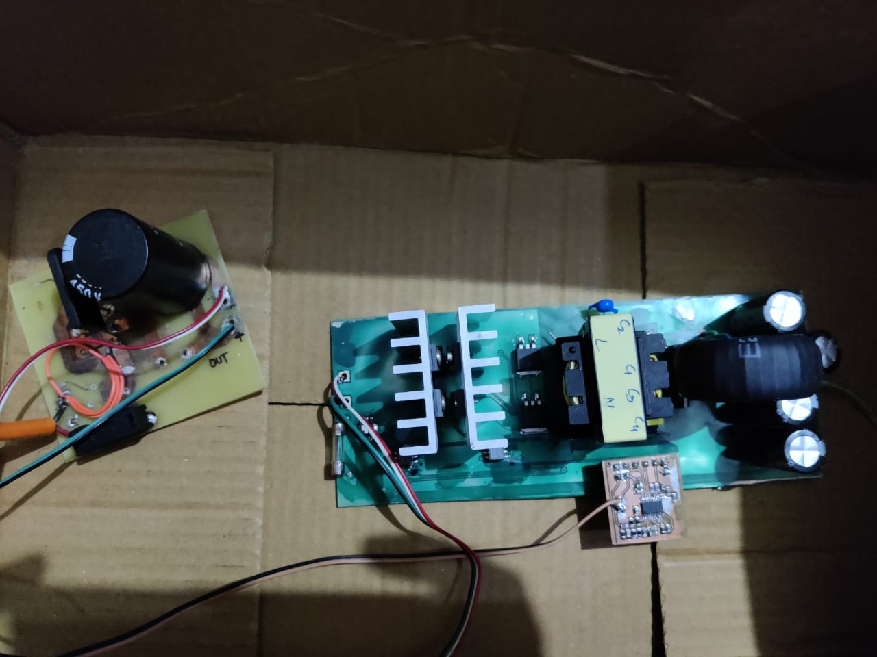
When we tested the board, the output showed 95mV and then blew up the component. 

When we checked, we found out that the Driver IC got damaged.

We checked the controller board and found that the ground pin of the UCC28950 is completely floating. ( image below)

The input to this controller board is a direct 12 V DC source.,

I am attaching the Schematic and the layout for the controller and the mainboard.

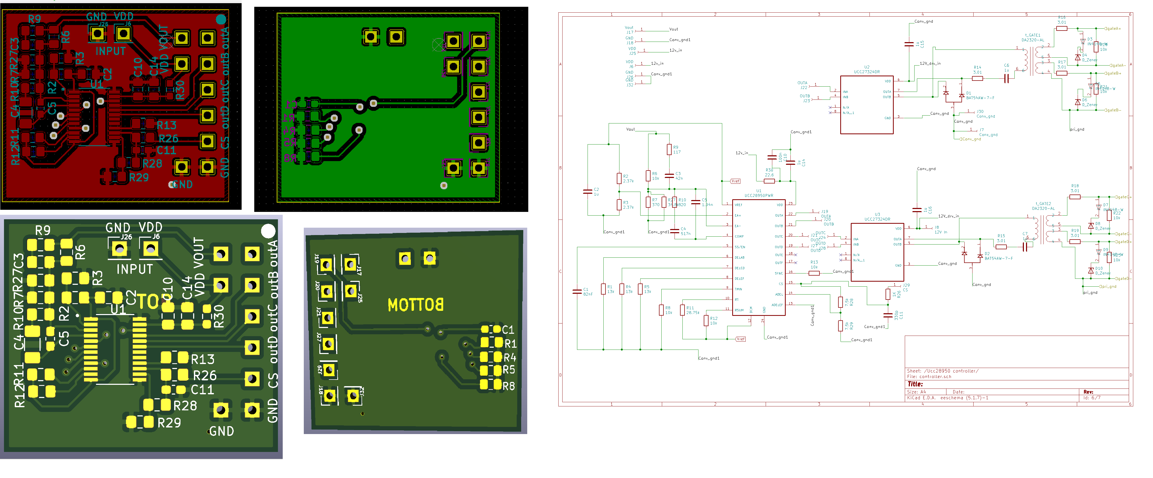
We revied the main board and found out that the out A on the main board trace was cut and the CS pin on the main board trace was cut.

We want to test the product phase by phase. 

1) the controller IC
2) the driver circuit

3) integration of the driver IC with the controller IC

4) the integration of the controller IC, driver IC and the mainboard.

Can you give a suggestion to implement this in a phase manner?

What can be the reason for Driver IC blowing up?


Thank-you

Warm Regards

Harini Krishna 

  • Hi, Harini

    I've assigned this thread to expert, pls expect a response by next Monday.

    Yunsheng

  • Hello,

    I looked at the pictures you have sent and cannot see how those planes are floating.  This is double sided board with plated through holes.  There are three through hle mounting locations that are shorting these planes.  

    You have made your own boards and even it you did not use through hole plating.  It looks like these are soldered with a wire going through and should be shorted as well.

    The layout you showing was used on the original UCC28950 EVM that was designed in 2010 and no one has reported issues with grounding.  You can find a find the latest user's guide for the EVM at the following link.  There are waveforms in this user's guide that can help you evaluate the design better.  You might consider ordering and evaluating this design to help better understand the operation of the UCC28950.  This design can also be modified to support your current design as well, to rule out layout issues.

    What causes FET drivers and FET to become damaged is current and/or voltage maximum ratings to be exceeded.  This will cause electrical overstress and cause the design to become damaged.   

    There are some design tools that you can use to check your design that you can find at the following links.

    Webench Designer: 

    Excel Design Tool:  

    Please not the excel design tool and 600W evaluation module were designed based on the equations from application note SLUA560C. 

    Regards,

    Regards,