This thread has been locked.

If you have a related question, please click the "Ask a related question" button in the top right corner. The newly created question will be automatically linked to this question.

LM46002: Buck boost inverter configuration: unstable output at 1A load

Part Number: LM46002

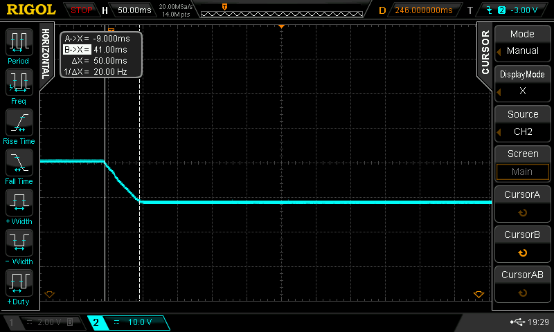
I am using LM46002 as an inverter in order to get -12V output when Vinput = +12V. The output voltage is correctly regulated at light load condition or low loads, but when I connect 1A load the converter output (-12V) is unstable and the converter is not able to regulate the output. I have realized that the LDO reference voltage (Vcc) drops below its UVLO (3.2V) and, in turn, the converter output is switched off. You can see the behavior of the output and LDO voltage in the following captures:

-12V output at 1A load:

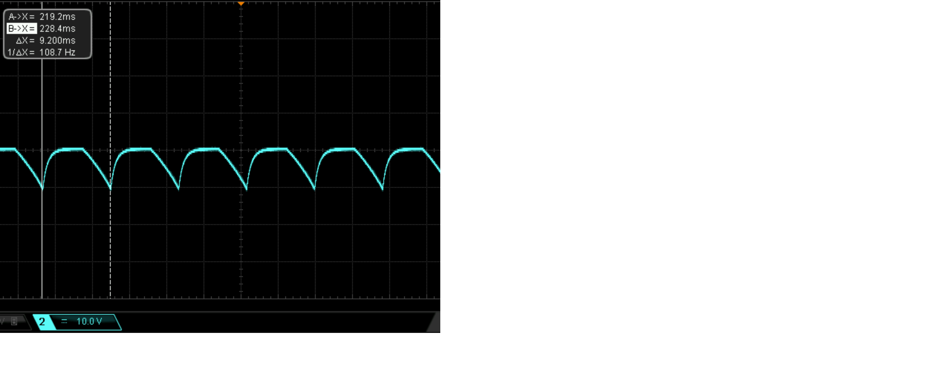
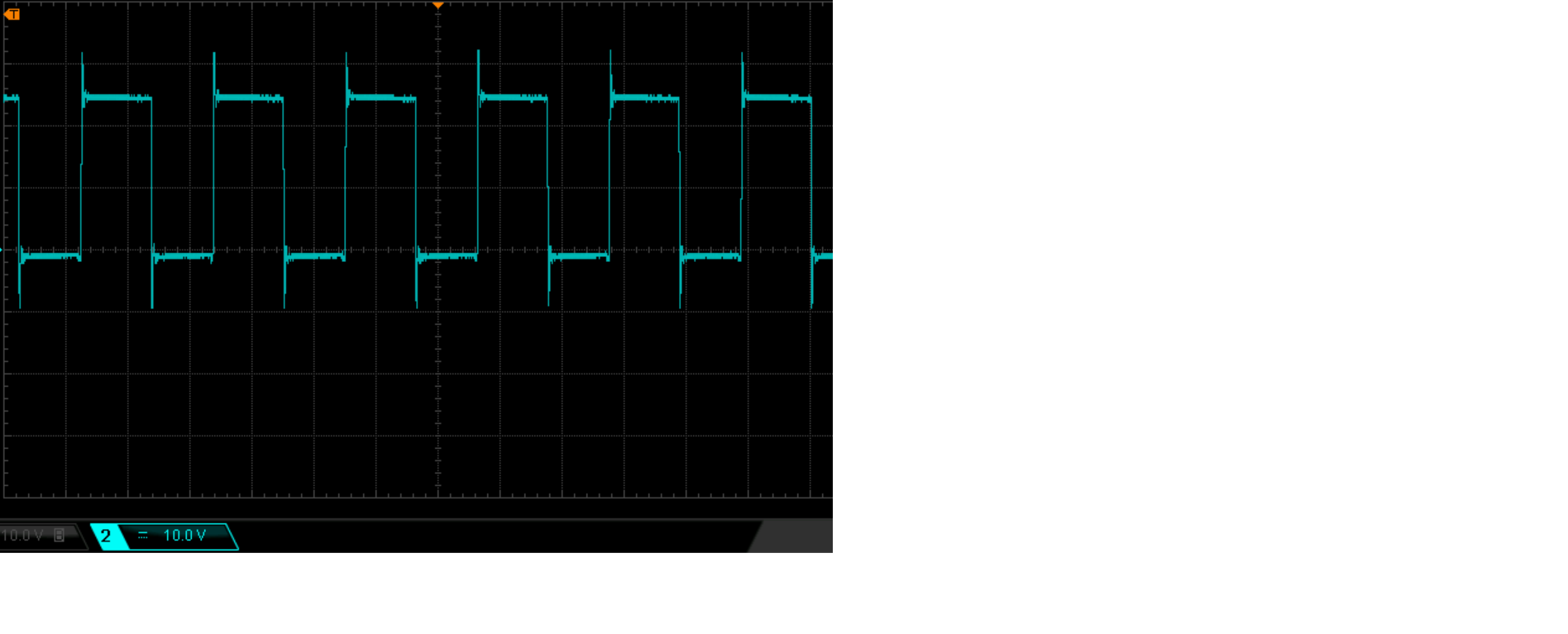
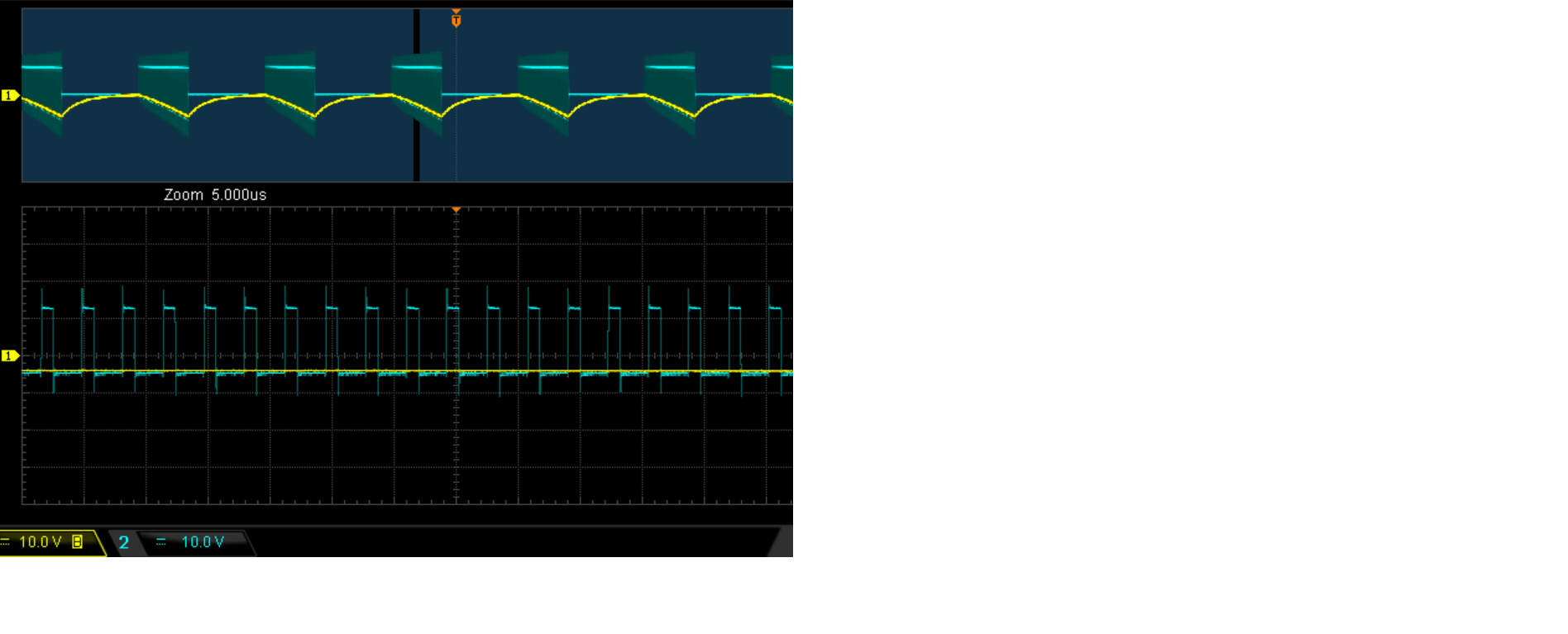
LDO voltage measured on Vcc pin:


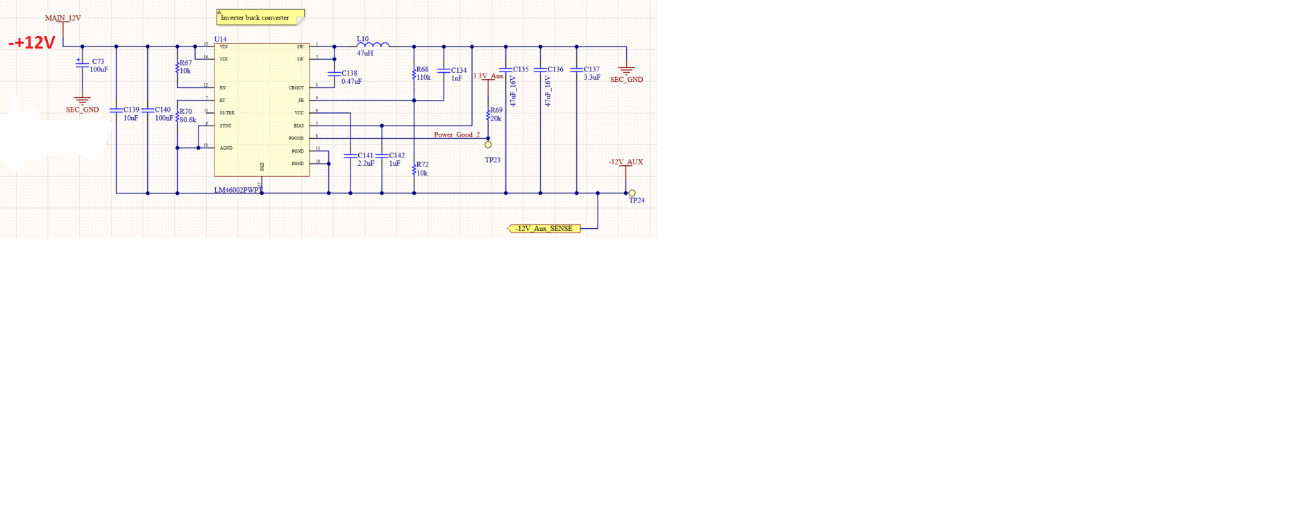
Why I get this behavior at 1A load? Please, see carefully the attachment (design schematic):


I am using the soft start by default of the converter. If I increase the soft start duration placing Css = 100nF, the output is correctly regulated to -12V at I_load = 1A.


I would like to understand the root cause of this issue. Thanks in advance for your support.

  • I attach again the pictures: 

    -12V output at 1A load (unstable) with no Css capacitor (soft start delay by default):

    Vcc LDO measured voltage:

    -12V output when Css = 100nF:

    Schematic:

  • Hi Manuel,

    What's capacitor type of C135 and C136? why use so big C134? is 1A load biased during output startup?

    L10 47uH should has saturation current >4.5A.

    Please turn on circuit at no load condition, then check SW waveform at 1A load to see if circuit working stably.

    BTW, the PWRGD pin can't pull up to 3.3V as this will bias PWRGD pin to 15.3V which is over maxim rating.

    B R

    Andy 

  • Hello Andy,

    my comments below:

    What's capacitor type of C135 and C136? They are ceramic X7R 2220 16V (part number: CGA9N3X7R1C476M)

    Why use so big C134? It is 1nF 0402 50V (part number: 04025C102KAT4A). It was calculated according to datasheet equations for Cff.

    Is 1A load biased during output startup? The load is connected before the converter is turned on, thus, during the startup phase is done with the load connected. In this case, at 1A load, the inverter output voltage is unstable as you can see in the following picture:

    L10 47uH should has saturation current >4.5A.  Yes, it was considered 5A of saturation current for the output inductor. Part number: SRP1038C-470M

    Please turn on circuit at no load condition, then check SW waveform at 1A load to see if circuit working stably. When the converter is turned on with no load condition, the switching node waveform is as follows:

     I think that the oscillation is due to DCM operation (no load condition). Under DCM operation, there is a resonant circuit composed of the output inductor and the parasitic capacitors in high side and low side transistors. When I connect the load (hot connection) , this oscillation dissapears and the switching node waveform is as follows:

     In addition, I captured the SW node waveform (blue) when the output is unstable (yellow) when 1A load is connected: 

     As you can see in the picture above, the SW waveform is stable as long as the converter output is turned on (zoom area) but it drops to 0 when the output goes to 0V.

    By summarizing.

    - If no load connected, SW node is stable but oscillations appear because of DCM operation. Do you think this is problematic? Do I need to reduce inductor current ringing during DCM operation? How can I remove this oscillations? May I need to add a damping resistor in parallel with inductor or a snubber circuit?

    - If 1A load is connected and the converter is switched on, the output is unstable but if I increase the start up delay the output is stable.

    - If a hot connection of the load is done, the output is stable.

    BTW, the PWRGD pin can't pull up to 3.3V as this will bias PWRGD pin to 15.3V which is over maxim rating. Yes, you are right, but "Power_Good" signal is connected to a voltage divider and, thus, the voltage does not overtake 15V on PWRGD pin.

    Please, read carefully my comments and give me your feedback. I am able to remove the output instability by increasing the soft start delay with  Css = 100nF but I don´t understand the root cause of this behavior.

  • Hi Manuel,

    The SW waveform at no load is correct, and it's hard to dampen the ringing because it's caused by the big power inductor.

    According to your testing result, the circuit can not drive 1A prebias load during startup, this is maybe caused by the inductor current valley can't drop below 2.05A at low-side ON time, the chip enter Hiccup mode and re-startup after 5.5ms, increase SS time will decrease the inductor current peak which also decrease valley at same time. 

    You can try smaller inductor like 22uH or smaller switching freq to see if the problem can be solved, but increase Css should be first choice.

    B R

    Andy

  • Hi Andy,

    thanks a lot for your feedback, it was very useful for me. Now I understand the root cause of the issue. 

    I will change the switching frequency and the soft start delay to reduce the inductor current during startup. I would prefer to keep the current inductor value to avoid a ripple current increase.