This thread has been locked.

If you have a related question, please click the "Ask a related question" button in the top right corner. The newly created question will be automatically linked to this question.

TL431: TL431 use as a constant current source

Part Number: TL431

Hi team,

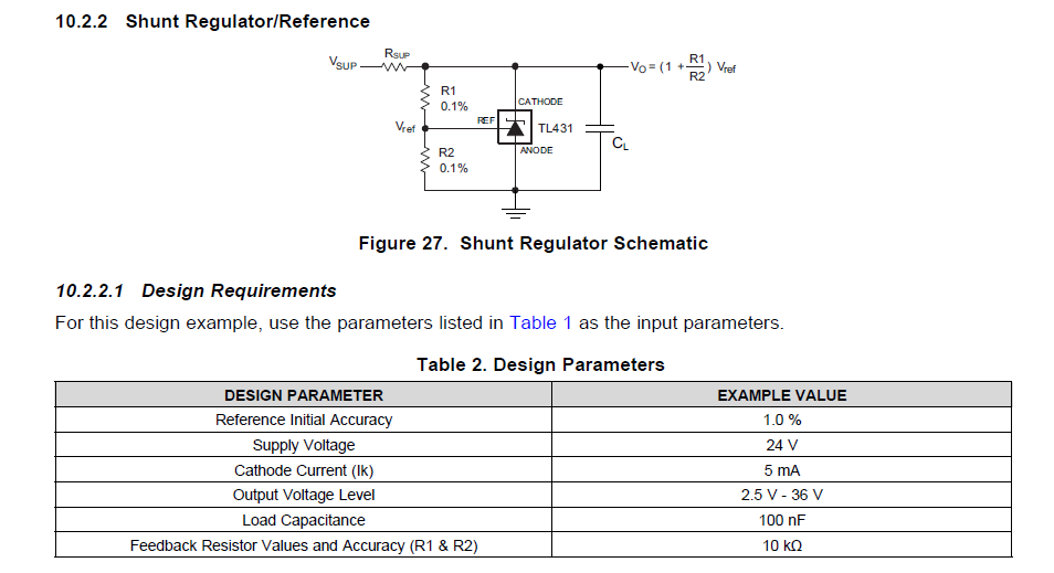
My customer wants to use TL431 as below example in our datasheet.

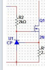
But to improve the BJT voltage endurance, they want to replace the BJT with a NMOS as below picture. Do you think this circuit can still realize the constant current source function? Thanks.

Best regards,

Wayne

  • Hi Wayne,

    Yes, the circuit will still give the customer a constant current source.  The current is still set by Vref/R.

    Ben

  • Hi Ben,

    Thanks for your reply. One more question about the TL431 sepc. as below picture in our datasheet

    In figure 10, it states a small-signal gain vs frequency. My question is:

    1. When should we consider this spec. when designing TL431? What kind of TL431 application needs this spec?

    2. In Figure 10,its DC gain is about 55dB. Is the curve in Figure 10 is tested based on Figure 11 test circuit? If not, where does this 55dB DC gain get calculated?

    Thanks.

    Best regards,

    Wayne

  • Hi Wayne,

    Depending on what frequency you are operating with the TL431, you should not use the TL431 if the applied frequency is over 1.5Mhz because the cross-over gain is 0dB. 

    Fig. 11 is the test circuit for fig. 10.

    Ben 

  • Hi Ben,

    Customer did one more test to check TL431 start up response. They built a circuit as below picture. 

    Customer set R1=R2=10k, Vsup=12V, CL is NC, Rsup=100ohm. 

    So Vo=5V, Ik=70mA

    The start up waveform is as below: Yellow=Vsup=12V, Green=Vref=2.5V, Pink=Vo=5V. We can see the start up time is 8us.

    While in our datasheet, we can see the start up time is only~2us. 

    So my question is:

    1. how can we explain the start up time difference between Figure 28 and customer's test result?

    2. What factor may influence the start up time? 

    Thanks.

    Best regards,

    Wayne

  • Hi Wayne,

    The waveforms/application does not match.  In fig 28, Vsup = 24V, whereas the customer's application appears to have Vsup = 12V.  Also, the Ik = 5mA for figure 28 but you stated Ik = 70mA.  

    My suggestion is to follow the design parameters in Table 2 and see if you can match the start-up response seen in Fig. 28.

    Ben

  • Hi Ben,

    My customer did another test in which they set the Rsup=1k. So Ik=(12V-5V)/1k=7mA. But the start up time we captured is much longer than the condition that Rsup=100ohm and Ik=70mA.

    So based on customer's test result, we can get a conclusion that the larger Ik is, the faster the start up is. 

    In our datasheet Figure 28, Ik=5mA but its start up time is 2us which is much faster than customer's test in which Ik=70mA. This is not aligned with our above conclusion. So I just want to check with you what's the relationship between Ik and start up time? 

    Best regards,

    Wayne

  • Hi Wayne,

    I am a little confused to why the customer is unable to repeat the results seen in fig. 28.  Is there a capacitive load on the output or something else that the customer has not shared with you?  

    Yes, increasing the Ik will reduce the start-up time because more current will charge up the internal capacitances faster.  Try increasing the Vsup to 24V and see if the start-up time decreases with Ik=70mA.

    Ben

  • Hi Ben,

    I developed a board on my own following the configuration in Figure 27 and Table 2.

    In test, Vsup=24V, Rsup=3.8k, R1=R2=10k, CL=not soldered.

    So Vout=5V and Isup=(24V-5V)/3.8k=5mA. And we get below start up waveform.

    CH1=Vsup=24V. CH2=Vout=5V. As you could see, the start up time is about 40us.

    While in our datasheet Figure 28, The start up time is less than 2us. So could you help check internally how did we get the Figure 28 test result?

    Best regards,

    Wayne

  • Hi Wayne,

    What is the slew rate of your supply?  In fig 28, the slew rate is very fast.  From the figure, the supply voltage slews from 0V to 24V in nanoseconds.  Is your power supply slewing that fast?

    Ben 

  • Hi Ben,

    My power source cannot raise up so fast. So I used another way. 

    Step 1: Let the power source output a 24VDC.

    step2:  Connect the power source GND line to the board GND network. Leave the power source 24V line disconnected to the board 24V input

    Step3: take the power source 24V line in hand and then touch the board 24V input. Then you can get a very fast slew rate on the 24V network.

    Best regards,

    Wayne 

  • Hi Wayne,

    What you describe is a hot-plug event.  Even with what you described, the rise time may not be in tens of nanosecond range.  Can you share a scope shot of what you have described?  I suspect the slow slew rate of your supply and the method you have described is still too slow and is contributing to the output slow slew rate.

    Ben

  • Hi Ben,

     I understand your point. I did the test again and zoom in the Oscilloscope scale to check the Vsup rise up time. Please see the waveform as below. When I use the hot-plug method, the Vsup(24V) rising time is only about 20ns which should be short enough. 


    Best regards,

    Wayne

  • Hi Wayne,

    The scope photo shows that the output rises and settles around 2V in 100nS which is what Figure 28 shows in the datasheet.  Have you tried using a different load capacitance on the output?

    Ben