This thread has been locked.

If you have a related question, please click the "Ask a related question" button in the top right corner. The newly created question will be automatically linked to this question.

LP87561-Q1: Seeing weird spikes and convergence issues in PSPICE transient sims when ferrite bead is present in the VIN_Bx input supply path

Part Number: LP87561-Q1

Hi,

I was running load transient simulations for certain test cases based on the PSPICE transient model and circuit available at www.ti.com/.../snvmaz9. I used the SPICE models of the actual capacitors that I intent to use in my final application. In addition, I also added the actual SPICE models downloaded from theMurata website for the ferrite bead part "BLM21PG300SH1D"  in the VIN_Bx and VANA input supply path which is the same part that's used in the TI EVM board for this part.

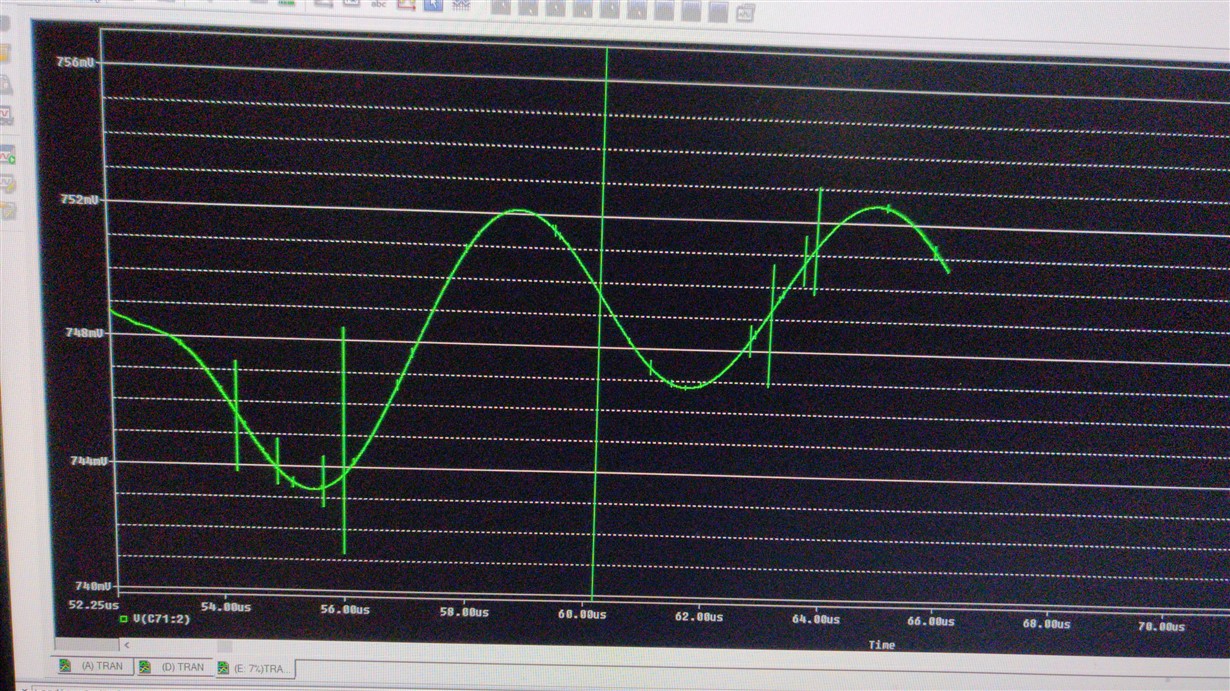
When these ferrite bead models are added, I see weird spikes in the VOUT waveform and later run into convergence issues in PSPICE transient sims. Waveform image below:

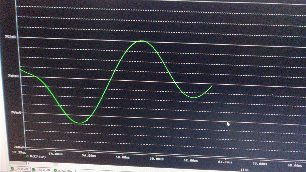
If I just short out these Ferrite beads, the waveform is clean and I don't see any convergence issues. Waveform image below:

My doubt is, is this a purely a simulation artifact due to the LdI/dt voltage ripple due to the Ferrite bead inductance when the buck draws in transient current from the input supply during the converter switching phases in conjunction with a perhaps not small enough max transient time step setting (currently it is 20ns, ie the same setting from the original PSPICE file that I downloaded), and in the real operational case these issues won't be visible? So I need not remove the Ferrite beads from the input supply path in my design?

Or is this a genuine concern even in the real life operation case and it is recommended NOT to use ferrite beads in the buck input supply path (even though I do see them in the EVM schematic)?

NOTE: My 5V input supply will be from either of the DC adaptors "MENB1060A0551F01" or "PPL36U-050" and I intend to have at least 500uF bulk bypass capacitors on the 5V supply (excluding the smaller decoupling caps):

Thanks,

Anoop

  • Hi,

    Do you have 10uF local input filter capacitor after this ferrite bead in your simulation model? You can use the ferrite bead on the input supply line, but 10uF input capacitor/ supply pin has to be placed directly close to the supply pins. Also, it is better to have single ferrite /inductor (preferred) instead of splitting each supply rails on input side. We recommend to have single VIN supply plane and connect all the supply inputs together at the device pin.

    Also, you need to be careful while using ferrites on supply line as it creates additional ringing during load transients and it may be EMC counter productive at certain frequency range. My recommendation is to use the ferrites only based on actual EMC testing. Also, you may need to try out 2-3 different ferrites.

    The issue you are seeing seems to be just the simulation artifact.

    Regards,

    Murthy

  • Hi,

    Of course I have added 10uF caps etc at the supply pins in the sims. Plus in the TI EVM board for this part, separate ferrite beads are placed for each supply. If a single ferrite bead is used, then the saturated and rated current specs for the part will have to be much higher I guess. I just followed the same scheme used in the TI EVM board, and the exact same model.

    I hope this is just a simulation artifact, since I'm assuming the EVM results didn't show such issues when it was tested at the TI end.

    Thanks,

    Anoop

  • Hi,

    Your simulation issue is just the simulation artifact. On TI EVM, there are huge capacitors (2x100uF) on each supply line after the ferrite bead, but in actual customer applications, you may have small capacitors (like 10uF-20uF) after the ferrite bead and hence, I recommended to have common LC filter to avoid any voltage differences between supply pins and VANA pins. Normally, it should be ok, but please verify on your application board to make sure that there is no significant voltage differences (~0.3V) between these pins.Yes, ferrites will derate significantly with load current and thats why inductor based LC filter is better compared to ferrites.

    Regards,

    Murthy

  • Hi,

    I'm following the same scheme in the TI EVM board, as shown below. I have the 100uF caps etc.

    Thanks,

    Anoop

  • Hi,

    Then hopefully it's an issue with a not small enough MAX transient time step I hope (using 20ns now, don't want to reduce it further in the interest of sim time). Will simulate after shorting out these ferrite beads since it seems like this is not expected in real life based on your feedback

    Thanks,

    Anoop

  • Hi,

    Thanks. Sounds good.

    Regards,

    Murthy

  • Thanks for the details!

    Thanks,

    Anoop