This thread has been locked.

If you have a related question, please click the "Ask a related question" button in the top right corner. The newly created question will be automatically linked to this question.

LM5060: LM5060. High temperature behavior

Part Number: LM5060

Hi

We are using LM5060.
This IC is located next to the hot spot on the PCB. Temperature of IC doesn't exceed 125C in steady state. 

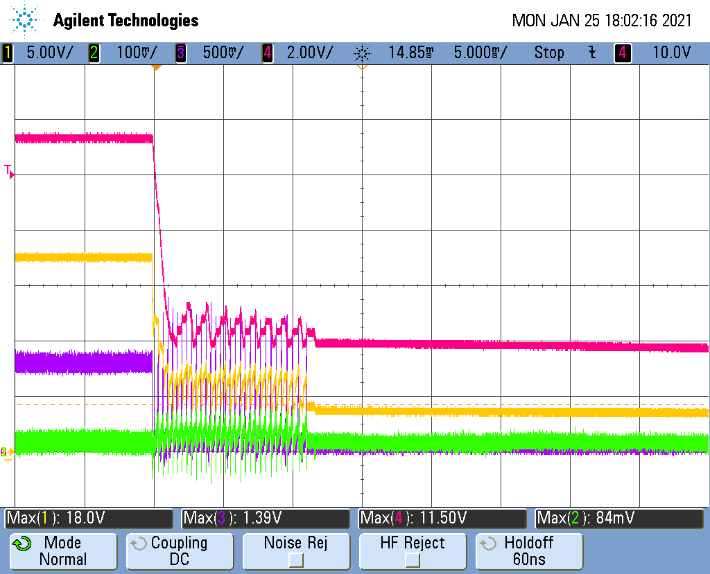
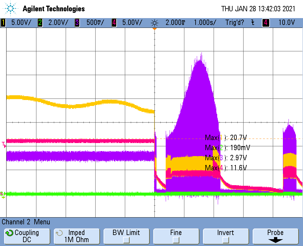
But during operation, the temperature can change very quickly. And when this happens, the IC starts constantly turning off and after a few minutes turn on the controlled FET.

IC doesn't latch, voltages on pins UVLO, ORP, EN, TIMER are within the limits necessary for normal operation.

This behavior is similar to thermal protection but I didn't find any information about this in the datasheet.

Does anyone know what state the IC is in? What can I do with this?

  • Hi,

    Welcome to E2E!

    Can you share the schematics for review.

    Also please share few test waveforms under the shut-off condition, please capture below nodes

    1. Vin, Vout, input current, timer

    2. GATE, Vout, input current, timer

    Best Regards, Rakesh

  • Thanks for your reply.


    This is the schematic (Nominal Vinput ~12V, Maximum Vinput = 20V)

    There are waveforms when shut-off occurs

    1). Yellow - Vin; Red - VOUT, Purple - Iin; Green - TIMER

    2). Yellow - GATE; Red - VOUT, Purple - Iin; Green - TIMER

    Spikes during shut-off are associated with the operation of the buck converter (12V->5V) which is connected to this bus.

  • Thanks for the schematic and test waveforms.

    I will review and get back in couple of days.

    Best Regards, Rakesh

  • Hi,

    Can you populate D48, add 1uF at the VIN_Fused bus and check again.

    Best Regards, Rakesh

  • 10uF was added at the VIN_Fused bus, D48 was populated. Behavior of the schematic remains the same. With D24 situation is the same.

    Yellow - GATE; Red - VOUT, Purple - Iin (1V=1.5A); Green - TIMER

    In an additional experiment D23 was added. In this case schematic latched. The latching cause is overcurrent protection because Vgs voltage gets lower and IC detects an increase of Vds voltages.

    Yellow - GATE; Red - VOUT, Purple - Iin; Green - TIMER

  • Thanks for the waveforms.

    Is it happening even at no-load also ? As you know the overcurrent threshold of this controller changes with Ron of the MOSFET which significantly gets increased due to nearby hot-source. To verify, can you increase the current limit threshold and check.

    Best Regards, Rakesh