This thread has been locked.

If you have a related question, please click the "Ask a related question" button in the top right corner. The newly created question will be automatically linked to this question.

LM3478: The gate drive current IG of the LM3478

Part Number: LM3478

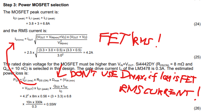
I am reading AN1484 desing guide. Step 3: Power MOSFET selection wrote on page 7: "The gate drive current IG of the LM3478 is 0.3A."

Datasheet does not include Ig parameter.

I only see Peak "Driver Output Current" at absolute maximum ratings.

Where this parameter come from?

URLs:

AN-1484 Designing A SEPIC Converter (Rev. E) (ti.com)

LM3478 High-Efficiency Low-Side N-Channel Controller for Switching Regulator datasheet (Rev. X) (ti.com)

Attila

  • Hi Attila,

    Thank you for your interest in LM3478.

    I think it used the equation 30 in 8.2.1.2.7 Power MOSFET Selection in the datasheet to calculate the drive current. However, the Vgsth information is missing in AN1484 so it's hard to verify. But check the note on the paragraph above the equation 30, the estimation just gives a rough idea.

    Thanks,

    Yinsong

  • Hi Yinsong,

    I saw the equation 30 in DS.

    Here is, what I think about this.

    Current through driver impedance I=(Vdr-Vgsth)/Rdron

    where

    Rdron is RDS1(ON) of 16 Ohm from DS

    Vgsth = 1.5V-2.5V at Si4442DY si4442dy.pdf (vishay.com)

    Vdr is Vin(min)=3V in this case. It could be 7.2V in case of Vin>7.2V

    So Ig=(3-1.5)/16=0.1A or (3-2.5)/16=0.03A

    This is far away from estimated input because it means 3 times switching power losses. 1.5W or 5W instead of 0.5W.

    So my final conclusion is this appnote is not correct for rough estimation.

    I note yet, that TI uses wrong formulas in guides to calculate FET conduction losses. The inductor rms/avg current is mixed with switch rms/avg current. e.g. equation 26, first part here.

    Wrong formula: Pdcond = IQ1 (rms) x RDS (ON) x Dmax

    Good formula: Pdcond = IQ1 (rms) x RDS (ON)

    where IQ1 (rms) is FET real rms current under full period. These ones are all of real FET Irms currents.

    Good formula: Pdcond = IL (rms) x RDS (ON) x Dmax

    where IL(rms) means real rms current waveform of inductors (L1 and L2) together under full period.

    IL(rms)=~IL(avg)=IL1(avg)+IL2(avg)=IL1(avg)+Iout

    Attila

  • Hi Attila,

    1. I think it considers the 7.2V case. But as I said, it is hard to verify.

    2. The IQ1 is misleading, it should refer to the combination of two inductor current, both peak and rms. Thank you for the note!

    Thanks,

    Yinsong

  • Just for audiance, who read this ticket.

    Please take attention, when use this formula, because equation 24 and equation 25 are wrong together!

    These wrong formulas are used together a lot of TI's datasheets and guides.

    Attila