This thread has been locked.

If you have a related question, please click the "Ask a related question" button in the top right corner. The newly created question will be automatically linked to this question.

LP3892IMM-3.3/NOPB output issue

Other Parts Discussed in Thread: LP3982, LM1117

Hello,

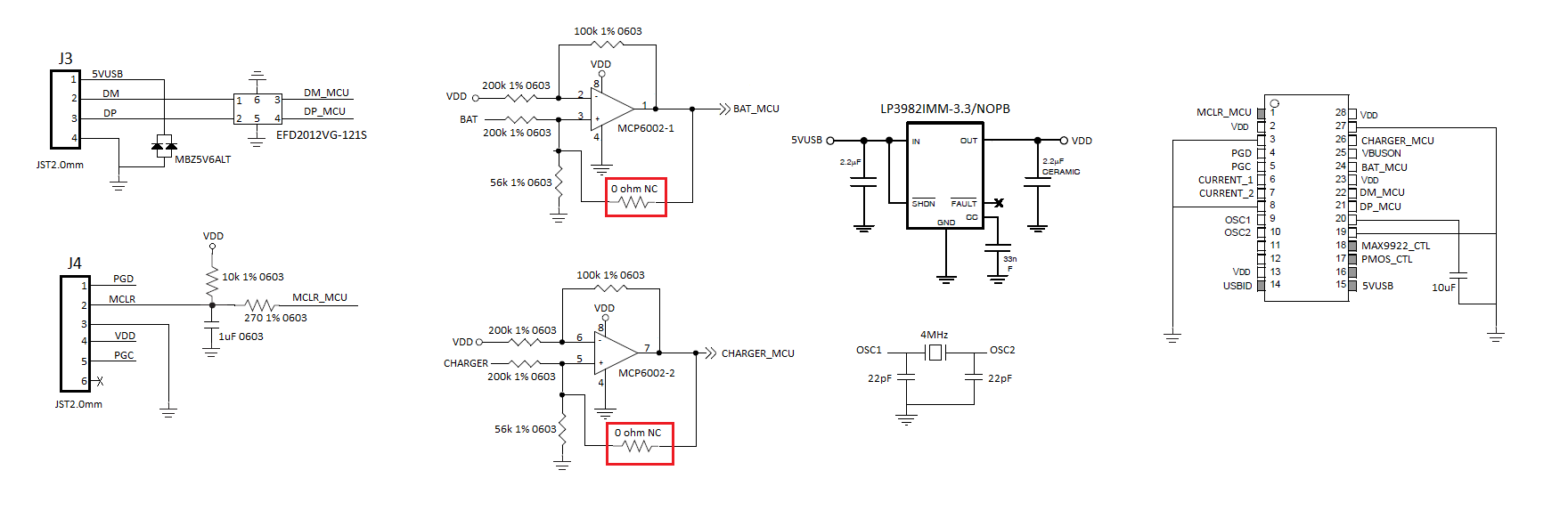
I am writing this post since I have an issue with the LP3892IMM-3.3/NOPB, the output voltage is not 3.3V it is actually 5.1V which is the input voltage. I read in a previous post that another person had the same issue with the 1.8V version (here the post title LP3982IMM-1.8/NOPB: Output voltage 3.3V instead of 1.8V written by Balasubramanian Periasamy). When the device is OFF I mesure no short circuit between the INPUT pin and the OUTPUT pin, as soon as the power is conected then a short cicuit appear.

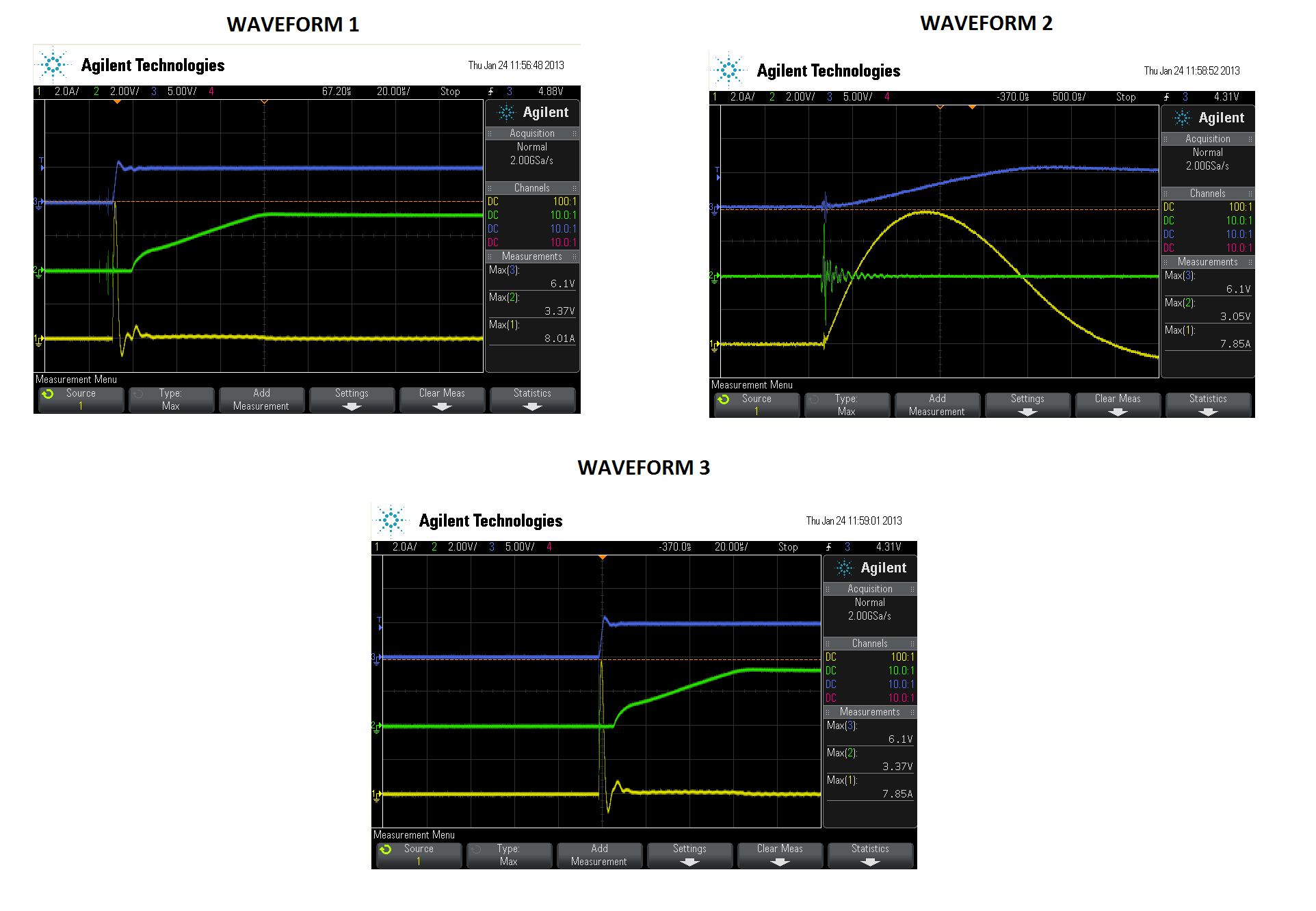
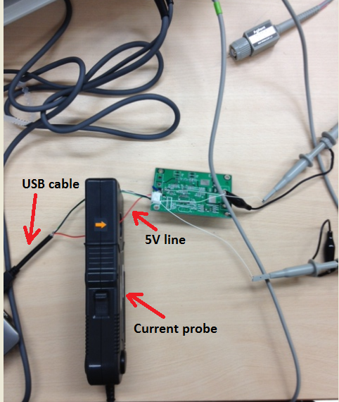
What is weird is that the fisrt time I turn ON the device the output voltage was 3.3V as expected, but then I disconnect and connect again and the output is 5.1V and since then the output keep the same. I check the PCB for a possible short circuit and there is nothing so I discard a PCB or layout issue. Since another person had the same problem I am wondering if you can provide more detail of what could be happening, is important to notice that my device is USB powered, as you can see in the attached file I am using the reference design in my circuit.

We are planning to use this IC is a new product and we expected to sell more than 20.000 units, as you can image this issue is a huge problem for us.

Best Regards

Mark Burger

  • Mark,

    It appears that the IC has been damaged somehow. We need to try and find the source of the issue.

    Have you seen this on multiple boards?

    Do you have any scope shots of the start-up of the LP3982 (Vin, Vout etc.)? Please supply these scope images showing multiple turn-on/ turn-off cycles or showing the scenario in which the IC failed. Can you also monitor the input current. It would be great if you could include this on the scope shots.

    Richard Elmquist


  • To add to the post from Richard ...

    If Vout value is very close to Vin then most likely the device PMOS pass-element has been damaged (shorted). This could be from over-voltage at the input, or reverse current through the PMOS body diode.

    If Vout value is tracking Vin, but not the same as Vin (perhaps a few 100's mV lower), then it could be a loss of ground to the device.

    For your referenced post (Thread ID: 198988) it was at least confirmed in the beginning that the issue was related to device pin 1 (i.e. OUT) being connect to the circuit board. Unfortunately there was no follow-up from the poster on what was ultimately found. Too bad for this community. You could go to your referenced post and reply with your own question(s). No idea if Balasubramanian will respond in a timely manner.

  • Donald, Richard,

    Thanks for your prompt response, I will try to get the scope waveforms today. Answering Richard question I only see this behavior on one PCB, we just receive the bare PCB and I hand solder the first sample. tracking the current will be quite difficult, I do have a current probe but maybe the resolution will not be accurate enough ( it is a 150A probe that we buy to test and measure in rush currenents).

    Just as aditional informaction, I replace (by hand) the LP3982 with a LM1117MPX-3.3 and it works perfectly, everytime we power the board the output is 3.3V. As I said before the input 5V comes from a USB port so I assume the voltage and current overshot should be minimum.

    Keep you posted!!!

    Mark

  • Donald, Richard,


    I had done the test you suggested, it looks like the problem was on that particular PCB I was using. I assemble a second one and the regulator is working fine so far, the previous one even with the LM1117 does not work, it start to get very hot after some testng. Right now we are testing the second piece, as soon as I have more information I will post it.

    Attached you can find the scope waveforms, I only have one concern and your expert opinion is more than welcome. As you can see the inrush current is quite high, around 8A, the pulse duration looks to be around 5us. I test connecting the PCB to my laptop's USB port, that is the way it should work this device (powered from a USB port). I have the following questions:

    1) Do you think such inrush current may damage the LP3982?

    2) If so, Do you know non expensive way to lower the inrush current?

    3) As you can see in the picture waveform2.png there is some ringing (transient) at the LP3982 output, is this normal?

    4) I also make a stress test by connecting the PCB to my laptop laike 20 times, at the end the output voltage was still around 3.2V. Do you think I could have a problem in the future?

    Best Regards

    Mark

  • " ...  the input 5V comes from a USB port so I assume the voltage and current overshot should be minimum ..."

    Personally, I would not make that assumption.

    LM1117MPX-3.3 (SOT-223, Max Vin 20V, bipolar) is a totally different animal from LP3982, having a higher Abs Max Vin. So, this substitution could suggest that over-voltage transient might the problem.

  • Q1) Do you think such inrush current may damage the LP3982?

    A1) I don't think the current is actually through the LP3982 unless you measured current into the Vin pin. Not sure where you measured the input current, but based on polarity I'll guess you measured near the USB connector (red wire?) closest to the PCB. If that's the case then this is likely inductive kickback from the USB cable and the inital charging of the input capacitor coming to an end. But with USB cable power using a twisted pair I am surprised to see an ampltude this high.


    Q2) If so, Do you know non expensive way to lower the inrush current?

    A2) Typically a low value series resistor between the USB connector and Cin will provide damping. Essentially a low pass RC filter. Ferrite bead could be another option.


    Q3) As you can see in the picture waveform2.png there is some ringing (transient) at the LP3982 output, is this normal?

    A3) If this right at the time where Vin is initially applied, this is generally typical but is not due to the LDO as Vin is not high enough for the LDO to be operational. Ideally you would like to have a smoother start-up on the input. to reduce this.


    Q4) I also make a stress test by connecting the PCB to my laptop laike 20 times, at the end the output voltage was still around 3.2V. Do you think I could have a problem in the future?

    A4) Unknown. 20x on one USB port is not a very substantial sample size, unless this will only be connected to your laptop. The dynamics of the USB ports, and possibly the USB cable, could be a substantial variable out in the rest of the world.


  • Donald,

    Thanks for your comments, here some answers to your questions:

    1) I actually open the USB cable in order to measure the current, our current probe is quite big. So actually they were not twisted, you really think this can help to lower the inrush current?

    2) I measure the current directly on the red wire, using the scope probe (clamp type), I am attaching a picture of my test enviroment.

    3) I test again adding the ferrite you sugessted, the current peak remain almost the same (around 6A).

    4) You are right that 20 times is not a substantial sample size, this device is going to be connected to different computers. Actually we are planning to produce around 20.000 pieces of this device, each one will be connected to a different computer system. But at least can give an idea is the design is prone to failure, I was worried that it was since not even having the PCB completely assembled the LDO was burned.

    4) I was checking on the internet and I found another regulator from TI that I would like your opinion, is the TPS78833. It says is a 150mA LDO with inrush limiting circuitry. What is your opinion on this IC? You think it might be suitable for my application? Do you know if TI has a LDO like this one but with a higher output current?

    Best Regards

    Mark


  • I have no direct experince with TPS78833, but a search of this Linear Regulators forum shows no complaints, so that's something.