This thread has been locked.

If you have a related question, please click the "Ask a related question" button in the top right corner. The newly created question will be automatically linked to this question.

MPPT solar charger design

Other Parts Discussed in Thread: BQ24210, BQ24650

hello,

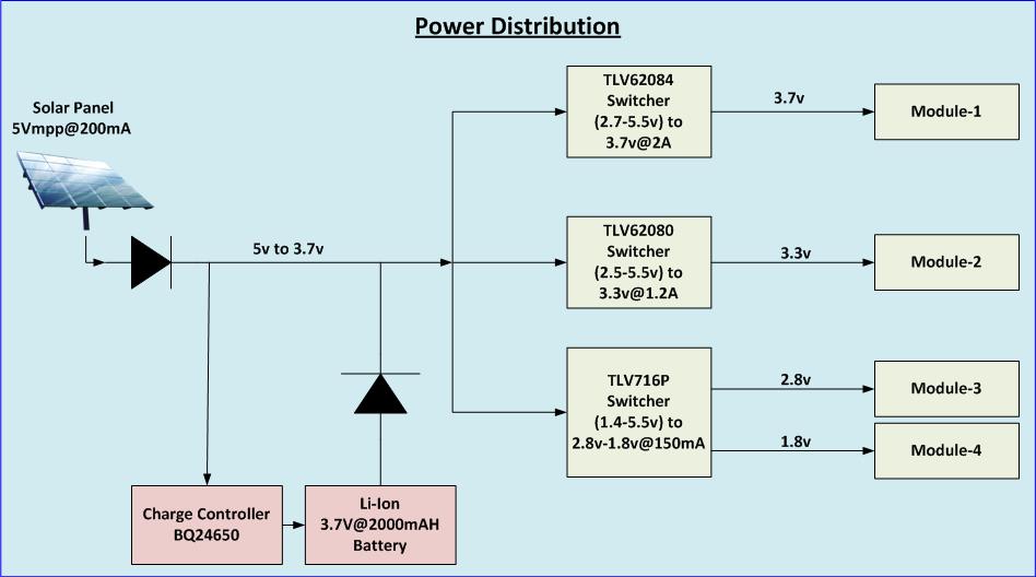
We are working iOT based design with solar power design.

i require MPPT solar charge controller which is suitable for my power consumption requirement.

my device power consumption requirement is 3V@700mA

and also connected 4.2@2000mah battery for battery back up

you have better solution please  suggested us suitable MPPT based solar charge controller for our system power consumption. 

  • If you solar panel can provide > 4.5V then I suggest bq24210 or bq24650.
  • Thanks for suggestion for solar charge controller.
  • thanks for suggestion.
    have u any block diagram which system load and battery also connected in BQ24650?
    kindly provide us.
  • The evaluation module (EVM) at www.ti.com/.../sluu444a.pdf has a simple way to provide system output by adding a diode.
  • Hello,
    We are working on solar based project with battery backup features.
    We have below requirement.
    battery type : Li-ion (3.7V)/ LiFePO4 (3.2V)
    Battery rating:3.7v@2000mAh
    System Load: 3.7@190mA/day but peak current 3.7@2A for 5sec
    Solar Panel :5V@200mA

    Right now we have selected BQ24650 charge controller and we have below queries.
    1. As we checked in datasheet, Bq24650 has feature of over voltage, under voltage , thermal and battery detection.
    So, Do we require external PCM circuit for battery protection?
    2. As per our system load, we need 3.7V @ 2A for 5 to 10 sec only . solar panel has only rating of 5V@200mA and battery
    rating of 3.7V@2000mAh.
    When system require 2A at that time charge controller can handle or switching load supply from solar panel to battery backup.
    after some time (in sleep mode), it will revert back to solar panel. Does our understanding is correct?

  • Hi Hiren,

    1. If your battery pack does not already have over-discharge protection, then you may have to add this functionality.
    2. You can connect a diode from the battery to the system, so if the system requires more power, then it will draw from the battery. Look at the schematic of the user guide: www.ti.com/.../sluu444a.pdf
    It will enter sleep mode once V(VCC-SRN) reaches 100mV and out of sleep when V(VCC-SRN) is 500mV.

    The battery will charge very slowly or not at all if your system requires average 3.7V@1.90mA. I suggest a panel that can supply more power.

    You need to verify what is the voltage range for your system, as the system voltage will be reduced due to the diode forward voltage.

    Thanks,
    Steven
  •  


    HI Steven,

    Thanks for suggestion

    We want to clarify above post our system load is 190mAh/day.it is summation of active mode and sleep mode current require in one day. If we calculate required current in one hour is 3.7@8mAh (190mAh/24). Here battery have rating of 3.7V@2000mAh . So, it provides battery backup for 10 days    ( 10days*190mAh=1900mAh)

    Our system working in two mode.

    1. Active mode require 3.7V@1.9mAh but peak is 2A for 5 sec in one hour
    2. Sleep mode require 3.7V@5.5mAh

    Below, Saw power distribution block diagram of our system.

    We have explored BQ24650 acherge controller but we have few queries as mentioned below.

    1. We think that max voltage of Li-Ion battery 4.2V so we set Vfb is 2.1v and BQ24650 always sense this voltage of VFB pin and compare with threshold 2.05V. So Charging will remain off till Vfb pin between 2.1v to 2.05v.It means battery voltage goes below 4.1V than again charge battery.

    2. Here diode mechanism is used for switching. If system load will work on battery backup than diode will be conducted. As per our block diagram, module 1 is working on 3.7V. So, battery will provide 4.2 - 0.5 (diode forward voltage) = 3.7V.

    Does our understanding is correct. 

  • Hiren,

    1. Yes you are correct about how the recharging works.
    2. Yes I understand your diagram and makes sense. However, for Module 1, you need to have a larger gap between 3.7V and the battery voltage. The lowest dropout for the switcher at 2A is (VIN-VOUT)=(~240mV + (inductor DCR * 2)), so a fair estimate would be ~300mV. You would need ~4V input on the switcher for it to supply 3.7V output.

    Thanks,
    Steven
  • Thanks for provide help