This thread has been locked.

If you have a related question, please click the "Ask a related question" button in the top right corner. The newly created question will be automatically linked to this question.

TPS61220: Datasheet calls for the FB pin to be approx .500V. Not so!

Part Number: TPS61220

I use 2 of these on a board, one for 5.0V, and the other for 3.3V. I set the resistors appropriately. 3 boards were built up, and the supplies tested. Out of 6 parts, one gave me the correct voltage - 5V, and the other 5 were all over the place. The one correct part regulated reasonably well, the other were far from spec. The 5 "off" parts had the FB pin ranging from about 0.22V to 0.98V - not the 0.5V as per the data sheet.

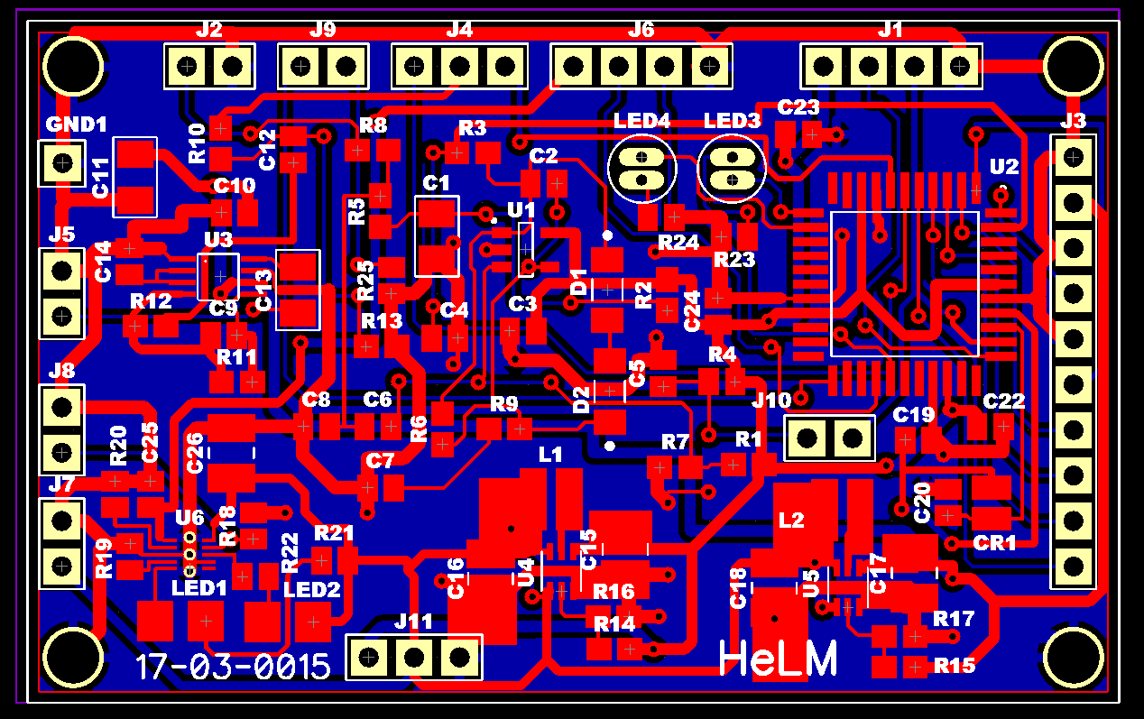
The layouts are reasonably close to the suggested layout. Both input and output  caps are 10uF. The resistor selection was per that suggested in the data sheet.

Can anyone tell me why these parts fail so miserably? I cannot see anything that I've done that is in great variance with the Datasheet.

  • The problem is a bit different from what I first thought. With no load, most of the parts appear to function. However, any load causes the FB pin to drop in voltage, with the output also dropping. It appears that these parts cannot handle any meaningful load at all? This makes no sense.
  • Can you post your schematics? What is tour input voltage? What type of output current do you need? The maximum output current is dependent on the input voltage.
  • HI John:
    The schematic is that shown in the data sheet. Values were determined by the TI design program. I set the input from .9 - 1.5 [actually will be a single cell Ni-MH. I use two if them, one for 3.3V and one for 5V. My current will be under 30 mils for each, but for design purposes, I used 50 mils. I directly connect the EN pin to Vin, slightly different from the suggested layout.
    This should be textbook, but it isn't turning out that way. Given that I followed the data sheet so closely, I just do not understand whey they do not work. For test, I used 1.3V input, and at a current out of as little as 5 mils, the output V drops to about half of what it should be. No load, the FB pin is about .9V in most cases, far from the data sheet spec.
    I am pulling my hair out [what little I have left], because There just isn't much to check or change.
  • Hello
    improper layout could cause this problem. could you share the image of the layout of TPS61220? please also share the schematic and part number of the inductor.
    and you can apply an EVM for reference.
  • Jasper, I am happy to post both board and schematic, however I do not see a way to post files on this forum. If someone can assist, I will post them.
    Also, I do not understand the phrase "apply an EVM for reference"
  • you can select "use rich formatting" and insert "media"
  • Here is the schematic [the third image]  [the relevant part], plus two board files. "current board" [the first image] is the board I am working with, and having trouble with. The "reworked board" has been modified to more closely resemble the recommended layout [the second image].

    I am not anxious to have the reworked board fabricated unless I am reasonably sure I am dealing with a layout problem, and not something else. If it is a layout issue, I then presume that this is a parasitic inductance problem with the leads?

  • I should mention, the schematic shows the TPS6122. I am actually using the 61220
  • to confirm the problem is really caused by the layout, we can do some experiment with the current board.
    1. in the current board, place a 0603 package 10uF capacitor next the IC's VOUT and GND pin, connect the capacitor and IC directly with solder
    2. place a 0603 10uF capacitor close to the VIN pin of the IC
    3. make sure using 4.7uH inductor and the connection is good.
    4. measurement the waveform of the VIN, SW, VOUT, and the inductor current when the IC doesn't act normally.
  • Jasper, it took some doing [73 year old eyes trying to hand solder parts as small as a dot!], but I succeeded, plus I ran a heavy wire from the ground side of the Vin/GND to the ground side of the  Vout/GND cap to beef up the in/out ground.

    With no load, I get reasonably good regulation from 0.65V in to 2.9V [I didn't want to go higher].

     However when I add a load - about 20ma if I were getting the proper output, My power supply goes into current limiting, which I set for 100ma.

    This is roughly the same as without the extra caps and wire.

    I am using a 4.7uH inductor, as suggested, the same Coilcraft that is suggested. Yes, it bis securely soldered.

    I didn't attempt to measure the DC current through the coil because I do not have any probes small enough to safely get in there.

    AS to wave forms, I do not see anything that resembles the data sheet.

    Now I am just further baffled. I even tried to draw just 5ma load - same results. I have no hair left to pull out, so I need some other method to alleviate frustration!

  • i'll do my best to help! we need to find the root causes of the problem you observed, then we know how to solve the problem.
    i suggest you to apply a TPS61220EVM and some samples from TI.com, connecting the EVM to your system to check if the EVM can operate well in the system.

    about measuring the inductor current, you can insert an external wire in series withe the inductor, then measure the current flowing through the wire.
  • Jasper, I very much appreciate your assistance. I have ordered the EVM . As soon as I get it, I will do as you suggest.

    Regards,

    George

  • Hi Jasper:
    Instead of buying the sample board, I redesigned our board so that I was exactly copying the suggested layout per the data sheet. Got the boards in, built up two test boards, and guess what? THEY WORK perfectly!!

    My only comment to anyone using this type device. LAYOUT, LAYOUT, LAYOUT!!! There is a good reason for suggested layouts. Even the tiny inductance of leads can cause problems [at least that it my assumption why they failed with my first design.]

    Thank you, Jasper for your inputs