This thread has been locked.

If you have a related question, please click the "Ask a related question" button in the top right corner. The newly created question will be automatically linked to this question.

UCC28070: 3 phases PFC based on UCC28070

Part Number: UCC28070

Hello,

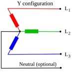
I need to design PFC with three phase input, Y connection (star connection: R, S, T, N - 4 wires) and one, common, 380V dc, non-isolated output.

Overall output power from 3 phases should be 9.9kW.

For equal power sharing between AC phases, I thought to use one UCC28070 based PFC on each phase (each input is between phase and neutral) and synchronize between 3 UCC28070 with an external clock source with 120 degrees phase shift and share between the 3 controllers the common signals according to multi controllers configuration connection according to figure 18 of the datasheet (identical to described topic in please, see an existing block diagrams in the linked topic, it describes my topology).

In my topology each UCC28070 based PFC should deliver 3.3kW, while this 3.3kW is equally shared between 2 interleaved phases of the UCC28070.

Operating requirement are as following:

Vin phase to return (effective voltage): 90Vac - 130Vac or 198Vac - 242Vac. It can be two separated designs, there is no need to support both input voltage ranges at the same design.

Output power from each UCC28070: 3.3kW (interleaving of 1.65kW par each switching phase of the UCC28070).

Overall efficiency: better than 98.5%.

EMI (conducted emission): per EN 55022, Class B.

The efficiency and conducted emission of the PFC are major goals, due to this fact I thought to build a bridge-less interleaved PFC.

According to SLUA517 there is a bridge-less design but there is no interleaving (the disadvantage is that the ripple cancellation is not available). 

According to the following publication, which based on UCC28070, the interleaved bridge-less PFC is achievable ( https://delta-q.com/wp-content/uploads/2015/02/AHigh-PerformanceSingle-PhaseBridgelessInterleavedPFCConverterforPlug-inHybrid.pdf ).

Questions:

1. Do you think that the equal power sharing between 3 phases is achievable in suggested configuration?

2. Is it better to implement a bridge-less topology or semi-bridge-less topology (with to diodes for return path)?

2.1. May be semi-bridge-less topology is better from EMI point of view?

2.2. In a case of semi-bridge-less topology may be there is a need to bypass the diodes with MOSFETs. Does bypassing MOSFETscontrol can be generated from the synchronization clock and PFC MOSFETscontrol (kind of subtraction of the two signals)?

3. Do you think that EMI requirements can be met (this is the reason that I am interested in interleaving function, in addition to power stress sharing between interleaved stages) in suggested topology (I plan separate EMI filter for each phase, each UCC28070 PFC) ?

4. For testing the idea of current sharing I am planning to synchronize between 3 evaluation boards of 300W (UCC28070EVM), do you see any problem with this connection?

5. If the suggested idea isn't good, can you please suggest any other solution?

Thank you,

Alex.

e2e.ti.com/.../478335

  • Hello Alex,
    Your system has 3 input phases R, S and T as well as a ground wire N which is sometimes called PE (for protective earth)
    or sometimes called Ground.
    An issue here is that you cannot draw current on this N cable.
    This is a requirement set by the relevant safety agency in order to prevent the user from electrocution. This Ground cable is sized so that it can handle twice the expected fault current and is twice the diameter of the R, S and T cables even though it is not conducting in normal operation.
    The diameter of the cable should give you an indication of the the seriousness of any potential failure here.
    I recommend that you check your safety agency requirements as well as your requirements for power factor and line harmonics for the type of product that you are developing before you proceed.
    Applications for the bridgeless UCC28070 have all been used with a single phase input.
    There are some product applications that allow you to use a 6 diode rectifier with the R, S and T phases followed by power factor correction of the rectified DC. You can achieve a reasonable power factor this way but the line harmonics are not very good.
    As far as I know there are no analogue pfc controllers that have been used in three phase applications with low line current harmonics.

    Also there is no 3 phase 90Vac-130Vac available.
    I think 208Vac line to neutral is the lowest voltage available and you should be able to design a single phase application with the UCC28070.
    Hope these suggestions help
    Regards
    John
  • Hello John, 

    Thank you for your reply.

    I think that here is some misunderstand in definition of "N" neutral. When I talked about 4 wires connection in Y (star topology, R=L1, S=L2, T=L3, N=neutral), I meant that "N" is the common point of star connection and not a "protective ground" (protective ground is in general is a 5-th connection). Please find a picture bellow. Additional source information: www.belden.com/.../3-phase-power-wye-it-matters

    In star configuration we can conduct current because an electricity company has a transformer from Y-to Delta (because high voltage in the street supplied from the electricity company on 3 wires, it means it comes from Delta generator).

    I want to operate in a single phase connection (from phase to neutral), while the supplied source is 3 phase Y connection (4 wires). In my idea I want to get equal power distribution between 3 phases (please the picture below). Due to the fact that each PFC operates in single phase configuration I need operation ability also at 90Vac-130Vac (can be separate design from 220V system). Because of the poor line harmonics I prefer to operate as shown bellow and not use a 3 phases rectifier (6 diodes)

    Do you think that the system concept is o.k., or see any potential problem?

    P.S. If system's concept is o.k., please see my questions from the first (original post).

    Thank you.

    Alex.

  • Hello Alex,
    If you wish to synchronise three separate UCC28070 pfc stages then you can use the timing diagram of Figure 18 in the data sheet as a guideline.
    You will need to generate a master clock with 3 outputs. The outputs being 120 degrees out of phase . Details for the SYNC pulse width, frequency and duty cycle limitations are detailed in the data sheet.
    With this configuration will be able to share power evenly between the three stages.
    All of the TI reference designs for semi bridgeless pfc are for single phase inputs and I have no further comments on your systems architecture.

    Regards
    John
  • Hello John,

    Thank you for your help.

    Alex.