This thread has been locked.

If you have a related question, please click the "Ask a related question" button in the top right corner. The newly created question will be automatically linked to this question.

UCC27714EVM-551: About cause of destruction of evaluation board

Part Number: UCC27714EVM-551

Hi,

When the load current was manually changed from 0A to 0.5A, the phenomenon that EVM was destroyed occurred.
The input side fuse is blown. And In the primary side FET, D and S were short-circuited.

I will describe the evaluation conditions below.
・EVM is the default state.
・Start-up / down sequence is tested according to Application note page 10 "Power On/Off Procedure".
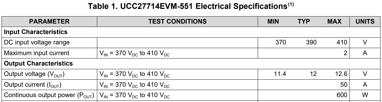
・Vout=DC12V
・Iout=0 to 0.5A (PLZ164W CR mode)
・VBIAS=12V (DC STABILIZED POWER SUPPLY)
・VBIAS2=12V (DC STABILIZED POWER SUPPLY)
・Vin(JP1)=DC375V (AC200V→PFC circuit→EVM JP1 (DC200V) )
・Customer connected the power meter to the input of the PFC circuit and monitored the input voltage and input current.
 However, the input current did not change even when the load was increased at about 0.6 A.

We are investigating the cause of the break.

1.Can this EVM output 0.5A@12V?
  I would like to confirm with EVM spec.


2.Could you tell us your expectations and concern about factors that EVM is broken?
  Please advice on the evaluation conditions I should check.

Best Regards,
Yusuke

  • Hello Tsukui,

    Thank you for the interest in the UCC27714EVM-551. Regarding the question if the EVM can support 0.5A at 12V output, the EVM is rated for output current from 0 to full load current of 50A so this condition is covered.

    Can you clarify the setup. The EVM power sequence is set up assuming 12V bias for the two bias supplies and 390V for the high voltage DC input. Is you setup providing the 390V from another PFC power stage instead of a DC programmable power supply?

    Be sure and follow the power sequence regarding the application of the HV supply and make sure the voltage is stable.

    There is an improvement we are implementing with the EVM build which helps with noise immunity of the EVM. We are adding 0.022uF capacitors across the primary MOSFET gate to source resistors, R10, R11, R16 and R17 which has been confirmed with the assembly contractor. I would recommend addition of these capacitors since your test setup may have additional noise if the 390V is from a PFC power stage.

    Confirm if this addresses your questions, or you can post additional questions on this thread.

    Regards,

  • Hi Richard,

    Thank you for your response and support.
    I check the PFC output and the following matters.
    "There is an improvement we are implementing with the EVM build which helps with noise immunity of the EVM. We are adding 0.022uF capacitors across the primary MOSFET gate to source resistors, R10, R11, R16 and R17 which has been confirmed with the assembly contractor. "

    There's one more thing I'd like to ask you about. 
    I have additional questions about EVM evaluation methods and startup sequences.

    1.Is it necessary to pay attention to the timing to input VBIAS2 (12V) after inputting VBIAS (12V)?
      After applying input DC375V and VBIAS voltage (12V) simultaneously,
      After waiting for 3 to 5 seconds, the VBIAS2 voltage (12V) was applied.
      As a result, there was a phenomenon that abnormal noise was generated and the output voltage dropped to about 6V.


    2.The customer connects short wires to the VREF, OUTB, CS and DCM pins on the evaluation board.
      They connect an oscilloscope to the wire for voltage waveform monitoring.
      Is this monitoring method is obtained become a cause of short-destruction?


    Could you give me your advice?

    Best Regards,
    Yusuke

  • Hello Yusuke,

    I have a couple of questions regarding the best power up and power down sequence for the EVM.

    There was a change to the EVM to address start up concerns. Is U4 on your EVM the ISO7240MDW, or the ISO7640FMDW?

    Does your setup allow Vbias and Vbias2 grounds to be connected? This would mean an isolated ground for the 390V input voltage?

    In all cases the suggestion is to apply the 390V until stabilized initially, and then apply the Vbias for the power up.

    If you can have Vbias and Vbias2 grounds connected, and have a safe setup for the user. Using the same bias supply for Vbias and Vbias2 so they start at the same time is preferred.

    For power up: Apply 390V first, Vbias second (if bias supplies are shared with the same DC supply. Vbias is the supply for the control IC. It is important to have this applied after the 390V input applied since the controller will execute the soft start sequence when Vbias is applied.

    For the questions on the waveform monitoring. Are VREF and DCM IC pins on the controller daughtercard? I do not see test points on the power board for these signals. Be careful monitoring waveforms with different ground reference points on the layout with scope probes, as the setup can setup ground bounce or noise on sensitive control signals.

    Confirm if this addresses your question, or you can ask more questions on the thread.

    Regards,

  • Hi Richard,

    Thank you for your kind support.
    Answer your question.

    ”Is you setup providing the 390V from another PFC power stage instead of a DC programmable power supply?”
    →Yes.
        I checked the output voltage from PFC, but there was no problem.
     PFC out put .pdf

    "There was a change to the EVM to address start up concerns. Is U4 on your EVM the ISO7240MDW, or the ISO7640FMDW?"
    →U4 was ISO7640FMDW.
     What kind of problem does this cause?

    ”Does your setup allow Vbias and Vbias2 grounds to be connected? This would mean an isolated ground for the 390V input voltage?”
    →Yes. 
     By the way, please explain why it is better not to use separate power supplies for Vbias and Vbias 2.

    ”For power up: Apply 390V first, Vbias second (if bias supplies are shared with the same DC supply. Vbias is the supply for the control IC. It is important to have this applied after the 390V input applied since the controller will execute the soft start sequence when Vbias is applied.”
    →Thank you for your advice.
        If DC input and Vbias are applied at the same time, Please tell me the cause of destruction.


    Best Regards,
    Yusuke

  • Hello Yusuke,

    I will answer your questions from the previous thread.

    There was a change to the EVM to address start up concerns. Is U4 on your EVM the ISO7240MDW, or the ISO7640FMDW?"
    →U4 was ISO7640FMDW.
     What kind of problem does this cause?

    The ISO7640FMDW provides an improvement to the power up sequence initialization. This allows more flexibility in the power up sequence.

    Does your setup allow Vbias and Vbias2 grounds to be connected? This would mean an isolated ground for the 390V input voltage?”
    →Yes. 
     By the way, please explain why it is better not to use separate power supplies for Vbias and Vbias 2.

    If you use separate Vbias and Vbias 2 it is important to apply the Vbias 2 before Vbias during power up, and turn of Vbias before Vbias2 during power down. If you share the Vbias supplies both bias supplies turning on and off at the same time is OK.

    The power sequence of the power up is to ensure the expected sequence events in a power converter. It is important that the controller starts with the input voltage stable so that the soft start sequence of the controller executes with the input voltage applied. Otherwise the power train may start in a condition with the controller at full duty cycle, if the controller bias is applied 1st.

    If the bias supplies can be shared, the start sequence should be apply 390V Vin (stabilize), apply Vbias which starts the controller soft start sequence. For power down, power down the bias supplies, remove the 390V Vin. Ensure the input voltage has discharged before touching the board.

    Confirm if this addresses your questions, or you can post additional questions on this thread.

    Regards,