This thread has been locked.

If you have a related question, please click the "Ask a related question" button in the top right corner. The newly created question will be automatically linked to this question.

TPS544B25: Concern about power up need to be confirmed

Part Number: TPS544B25
Other Parts Discussed in Thread: TPS544C25,

Hi,

Here is an application, the PGOOD pin is pulled up by 105K resistor to BP3 pin from TPS544C25.

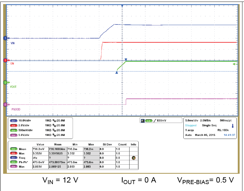
The waveform of EVM in datasheet page 86 is as below(EN is pulled up to BP3), there is no glitch in PG pin.


Here is the questions:

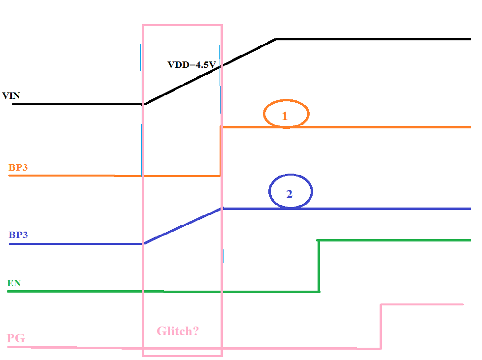
Is there any delay from VDD(4.5V) to BP3(ready to power up)?

Which curve would be the BP3 looks like in the figure below? 1 or 2?

The concern is when VDD is below 4.5V, will there be any glitch in the PG pin?

Thank you very much.


  • Hi Penn,

        I couldnt find this information readily in the datasheet. Let me find this information and get back to you.

    Regards,

    Gerold

  • Hi Gerold,

    Yes, I also try to find it in datasheet, but failed. This information is important for this application, please help check, thank you.

    Penn

  • Hi Penn,

         We are having this conversation offline by email.

    Regards,

    Gerold

  • Penn,

    The TPS544B25 has 2 internal linear regulators that run most of the electronics within the device a 6.2V gate drive regulator (BP6) and a 3.3V analog and logic regulator (BP3)  They are both run from linear regulators powered from the VDD input to the TPS544B25.

    Both the BP3 and BP6 regulators follow a current source limited start-up that typically resembles example 2 above, though the timing can be quite fast relative to the milliseconds soft-start of the Vin and Vout rising.

    With no voltage on the VDD, the PGOOD pin is internally self-clamped by a resistor pull-up from the PGOOD pin to the gate of the open-drain pull-down FET on PGOOD, this allows the PGOOD pin to hold the pin voltage low without any power at VDD.

    Once VDD is powered, the BP6 and BP3 regulators start to power-up.  The internal pull-down on PGOOD is powered from the BP6 regulators, and while it does not reach full pull-down strength until BP6  reaches about 4V, with a 105-k Pull-up resistor to BP3, there should not be an observable glitch on PGOOD on power-up unless the BP6 LDO is overloaded and held low - such as shorting it to ground, and even if it is, the self-clamping feature of the PGOOD pin should keep the PGOOD voltage below 0.8V with only 30uA (3.3V / 105k) of pull-up, so a logic comparator monitoring the PGOOD voltage would not see a glitch.

  • Hi Peter,

    Thank you very much for your detiled explanation. Crystal clear.

    Penn