This thread has been locked.

If you have a related question, please click the "Ask a related question" button in the top right corner. The newly created question will be automatically linked to this question.

TPS62866: TPS628660BYCG : Not able to read the VOUT Register 1.

Part Number: TPS62866

Hi,

When i am writing to VOUT Register 1, the voltage is changing as given in specific datasheet and i am able to verify that by probing. But, while reading the same register, i am always getting 0x00 as read value (i2c is being used for writing and reading.).Therefore, i have following doubts:

  • is it possible to read those registers.
  • is there a specific sequence for reading.

note:if you go through datasheet (http://www.ti.com/lit/ds/symlink/tps62866.pdf

  • Hello,

    Datasheet states: "Attempting to read data from register addresses not listed in this section will result in 00h being read out?"

    Can you verify on your side that you are reading at the good address here?

    Can you read register values from other addresses?

    Thank you very much for reaching out to us!

    Best Regards,

    Dorian

  • thanks for the reply but as per your reply, i came across following conclusion:

    • Datasheet states: "Attempting to read data from register addresses not listed in this section will result in 00h being read out?"  
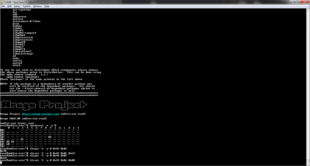
      • i am able to read the register from linux images.
    • Can you verify on your side that you are reading at the good address here?
    • yes, as shown in above image - the register is readable.
    • Can you read register values from other addresses?
      • There are only four registers
        • 2 Vout registers - type is not mentioned clearly.
        • 1 control register - type is mentioned as write only.
        • 1 status register - returning 0x00 (which is also default value).
  • Hi,

    I am not quite sure to understand what is the issue you are facing.

    You used 133k Ohm resistor at VSET. Setting startup output voltage at 1.0V, 0x78h in register 1 and 0x43 as I2C slave address.

    From what I can see in the 4 commands line there is in your picture, there is nothing wrong.

    1st line: You are reading the value of the output which is 0x78 set by R2D.

    2nd line: You are setting register 1 value to 0x64

    3rd line: You read the same value you just entered, 0x64

    4th line: You are setting register 1 value to 0x00

    Do you have any issue here? 

    Thank you very much!

    Best Regards,

    Dorian

  • the output screen that i have shared is with the pre-built binaries. Now, i am implementing on my own using i2c protocol for reading and writing.In this process i am able to change the voltages(which i am verifying through probing) but not able to read.

    • is there any specific sequence that i need to follow for reading.

    note:using windows platform and IDE as CCS.

  • Hello,

    The write and read sequence are different, see below:

    Can you check the information you are sending on the I2C bus? Did you add the Slave address like on figure 14?

    What is the sequence you are sending when reading?

    Thank you.

    Regards,

    Dorian

  • Hello,

    I haven't heard back from you. Are you now able to read from the registers?

    Do you need further help here?

    Thank you very much!

    Best Regards,

    Dorian

  • Hello,

    I will close this thread for inactivity.

    If you have any update please answer below this post to reopen the thread.

    Thank you very much!

    Best Regards,

    Dorian