This thread has been locked.

If you have a related question, please click the "Ask a related question" button in the top right corner. The newly created question will be automatically linked to this question.

BQ76930EVM: How do I connect a charger to the EVM circuit?

Part Number: BQ76930EVM
Other Parts Discussed in Thread: BQ76930, BQSTUDIO, BQ78350-R1

Hi,

I have an 8 cell (8S) LiFePO4 battery pack assembled and wired up to the EVM.  Power for the board is supplied by -ve from cell 1 and +ve from cell 8, i.e. Vcc is around 26-27V (because the cells are not fully charged).

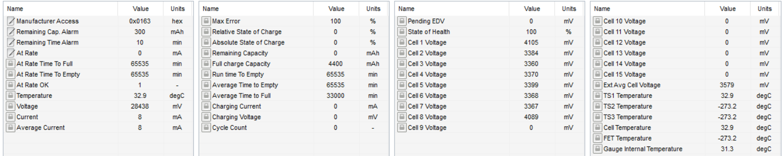
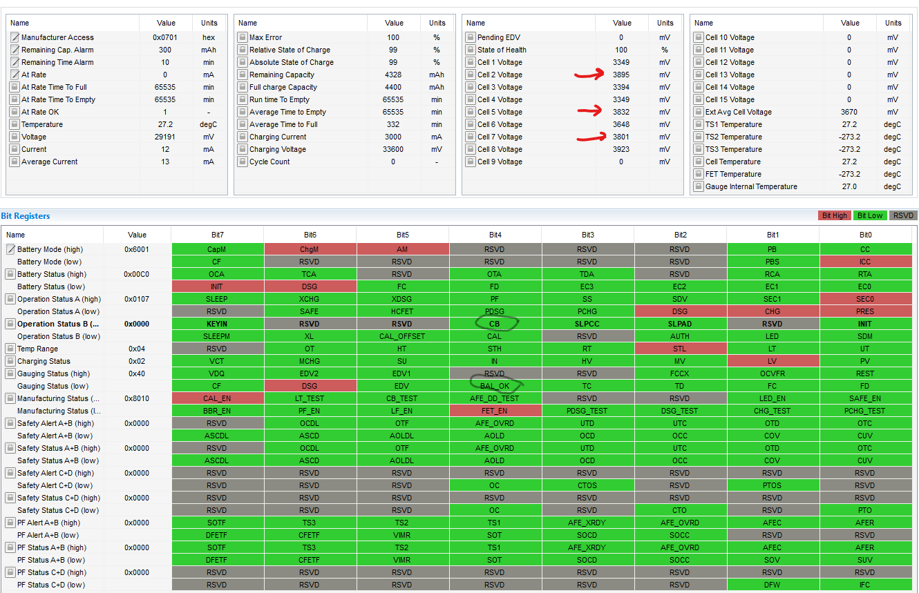
I have a DC power supply set at 29.2V and 500mA (which is the charging voltage for 8 cells) and I would like to connect this to the battery so that I can observe the EVM doing its cell balancing and over-charge functions.  However when I connect the power supply to the Batt- and Batt+ terminals of the board, I notice that the voltage for Cells 1 and 8 rise above 4V which is getting very close to their max of 4.2V - the remaining cells are all at a much lower value.  I've attached a picture of the register readings which shows this odd imbalance. 

Just wondering if I've connected the power supply (the charger) correctly for this exercise or is there some other reason why just these 2 cells should be reading so high?

Cheers,

Mike

  • Hi Mike,

    The charger needs to connect to the PACK+ and PACK- terminals on the EVM. This way the BQ76930 will be able to measure the current across the current sense resistor. Also, in the EVM User Guide there is a section (6.4) about reducing the cell count. Are you modifying the board as described in this section?

    Best regards,

    Matt

  • Hi Matt

    Thanks for replying to me.  I have already tried connecting the charger (power supply) across the Pack terminals but could see no difference in behaviour, i.e. no changes on the evaluation display and power supply indicating 0 Amps flowing.  To be clear, I have connected the +ve from the supply to the Pack+ and neg to neg.   Is this correct or are these meant to be reversed to 'simulate' charging?  I am somewhat confused by section 6.3 (Evaluating with Simulated Current) which mentions reversing the polarity.  I'm hesitant to do this unless I'm really clear on what can/will happen.  I have my power supply set to 29.2V and 500mA - the voltage is calculated based on the charge V for each cell which is 3.65V - the amps I deliberately set low to minimise damage if I had the configuration wrong.

    I do have the board correctly configured for 8 cells as per the Evaluation Board user guide instructions. 

    FWIW, I get an error message when I initialise the studio software.  Have attached an image showing the version I selected and the accompanying error message.

    I've also attached a couple of screenshots of the registers, one before the charger is attached, and the other after its attached.  So far as I can tell, there is no change to any of the displayed registers when I attach the charger.

    Cheers

    Mike


  • Hi Mike,

    The device should normally be automatically recognized by BQStudio. The most common reasons for it to not auto-detect is that the specific .bqz file is missing from the BQStudio config directory or the device is not booted yet on the EVM. However, it looks like you are able to communicate after you manually select.

    You also need to enable the FETs by clicking on the FET_EN button on the command window. The FETs are off by default after boot. In your register window the DSG and CHG bits in the Operation Status register are both set to zero which means they are disabled.

    Regards,

    Matt 

  • Hi Matt

    Can you be a bit more specific on the register settings please. To me it appears that CHG is ON already?

    DSG is OFF as are XCHG and XDSG. If I'm correct then both XCHG and XDSG need to be off unless I want charge and discharge to be disabled. With the current settings it looks like charging IS enabled while discharge is NOT enabled.   What am I missing here?

    Edit: I've just realized I've been reading the register colour codes the wrong way. I assumed that GREEN was ON, i.e. bit high.  Please ignore this post.

  • Hi Matt,

    Switching on the FETs has helped insofar as the studio now shows a regulated charge being applied to the cells.  When the charge cycle started, I noticed that the CB register was set to 1, indicating that cell balancing was occurring.  However, it has not been turned off and the cell levels are clearly nowhere near balanced.  I also can see that the BAL_OK register is low which, if I understand the doco correctly,  will prevent balancing from occurring.  So how/why did CB turn off? and how do I re-enable CB?

    Cheers,

    Mike

  • Hi Mike,

    If you use the BQ76930 with your own MCU, the MCU has complete control over cell balancing for each cell. On the EVM, you are using the BQ78350-R1 as the controller which has its own cell balancing algorithm. The BQ78350-R1 will only balance during charging and within a set voltage range. There is a chapter on Cell Balancing in the BQ78350-R1 Technical Reference Manual: http://www.ti.com/lit/pdf/sluubd3

    Best regards,

    Matt

  • Thanks Matt. I'll take a closer look at the section you've referred to.

    Cheers

    Mike