This thread has been locked.

If you have a related question, please click the "Ask a related question" button in the top right corner. The newly created question will be automatically linked to this question.

UCC21710-Q1: TINA simulation-MOSFET not driven low unless -ve voltage given at input

Part Number: UCC21710-Q1
Other Parts Discussed in Thread: UCC21710,

Hi,

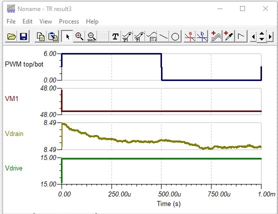
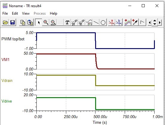
UCC21710 does not seem to drive the gate to low unless provided with negative voltage at input in simulation.

Drive voltage still high at 0 V input. 

It works fine if I apply negative voltage.

This is my simulation file: MOSFETDriverM.TSC. Is there something wrong with the simulation or does UCC21710-Q1 actually require negative voltage to pull gate to low?

Regards,

Ayman

  • Ayman,

    UCC21710-Q1 does NOT require negative voltage, you are correct. That is bizarre issue and most likely some nuance with the model and the schematic you have.

    A few points on the design i noticed

    * please check your DESAT circuit. I am not sure why its tied to OUTH

    * FLT_N pin should be pulled up to VCC. You should monitor this because in your schematic you are having fault each cycle. Thats why drive is going low at all.

    * When running your schematic even with negative voltage on input, there is a fault condition and in fact it would only work for one cycle. The fault condition must be corrected.

    * CLMPI shouldn't have a resistor on it, tie it directly to gate. ( this would matter in final PCB)

    Please check the following simulation i have run based on yours.

    I first seperated the grounds GND and COM by voltage source. Then ran with 0-6V ( no negative on input) successfully.
    I then removed the voltage source and tied the jumper directly to gnd. Sim ran OK.

    Then i tied the low voltage grounds back to HV ground by ground symbol. Sim ran OK. Surprisingly this was not the case initially.

    I would suggest first , simply seperate LV and HV ground by VDC source, or break them somehow, and then try connecting back directly like i did.

    Try these steps and let me know if you still having issues. If you still have issues probe RDY/FLT as well so we can see what of fault/uvlo condition being produced by the model.

    Best

    Dimitri

  • Dimitri,

    Thank you for your reply. I tried following the steps you mentioned but it didn't work for me. I still seem to get a fault each cycle.

    Regards,

    Ayman

  • Ayman,

    Try my modified schematic, as attached.

    Best

    Dimitri

    8182.MOSFET_DriverM_dimitri.TSC

  • Dimitri,

    Thank you for the help. It seems I inserted a Voltage source only between a single pin and ground rather than between the 2 grounds when I tried your solution earlier.

    Regards,

    Ayman

  • Ayman,

    Even i almost did that when i was checking. Glad we got it solved.

    Best

    Dimitri