Other Parts Discussed in Thread: BQSTUDIO
Hi there,
Recently I had purchased a BQ25713 EVM and had tested the working of the same with the help of the guide given out by the TI.
The datasheet of BQ25713 was referred to set the configuration to the EVM. The complete working of the EVM with a battery pack and system was tested and verified.
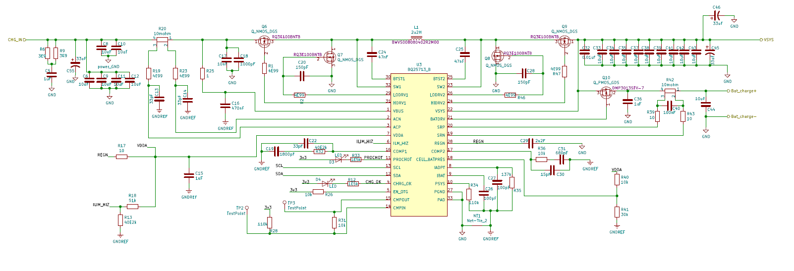
After understanding the working, We have developed custom pcb using BQ25713 exactly as EVM schematic, which has been posted below.
The working of the pcb for the given schematic was verified with a few sets of same boards. The components used for pcb was same throughout the batch . But, one of the board of the same batch was not able to charge the battery pack. Probable reason found out while debugging the board, was that the mosfet Q6 doesnt seem to be switching. The voltage between drain and source of mosfet Q6 in this particular board is 12.3 when 14 volts was given on input from charger whereas in the other WORKING boards, its 1.7620 V with same input .With charger connected and battery disconnected, the system voltage observed was 1.24 V(instead of12.3V which was set using using bqstudio also the working of the mosfet was verified by verifying the diode drop and Drain source resistance). This part seems to be causing the whole issue as the Vsys voltage in the faulty board 1.3V whereas in that of other working boards, its 12.3 V and the battery pack doesnt charge even when supply voltage is given. Some of the other observation are that REGN is giving regulated 6V output properly and when the battery pack is connected the VSYS voltage is equal to pack voltage(which is expected and correct) irrespective of the charger source being connected or not.
Just wanted to know what could be possible reason for this behavior of the board.
Thanks in advance!!.