This thread has been locked.

If you have a related question, please click the "Ask a related question" button in the top right corner. The newly created question will be automatically linked to this question.

LM5163: input power transient issue

Part Number: LM5163

Hello,

I recently designed a board using the LM5163 as a first step in the DC/DC conversion from the input voltage of 40-80V. It takes it down to 12V, and then I have a 12V/5V and a 5V/3.3V converter on board as well.

I am applying 48V from an AC/DC power supply and using a breaker switch to let power go to my board (after the AC/DC supply is already turned on).

When I flip the switch, I can see on my 5V and 3.3V lines some nasty transient spikes that go both positive and negative. This is before the LM5163 even starts working, I think. 

Is there any way you guys can help me to find out if the LM5163 chip or layout is causing this, or if my layout is bad somehow? I can share schematics and PCB files upon request, but what I wanted to show is this transient I recorded on the scope on the 5V line shortly after power up. 
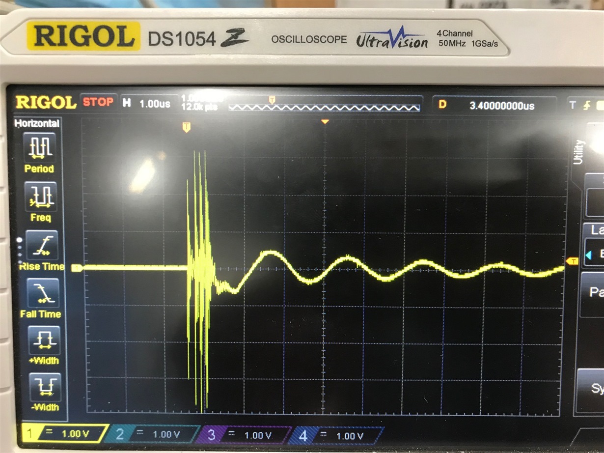
I think these transients killed my microcontroller because it was working the first few power-ups, but eventually it started to heat up instantly. It has a negative input rating of only about -0.3V, so I think the transients I'm seeing are much worse than that. 

Is this expected behavior when hard switching on power to the device with a physical switch? 

If so, is there a good way to stop this? I tried lots of different capacitors and filtering strategies, and RC snubbers, etc., but I can't seem to get rid of this. I'm not sure if this just happens and it's so transient that it's not important, but hoping to figure out more about it. 

  • Hi,

    The first suggestion is to add high-frequency capacitance or bead after the breaker switch and pay attention to the voltage rating of the capacitance or the current rating of the bead.

    Besides, could you please share the schematics and PCB files? Then we can have more suggestions.

    Best regards,

    Wendy

  • I have attached the gerber and pdf files of the layout, and also a schematic of the project. 

    I made the project in KiCAD and I can also share the KiCAD file itself, if that would be useful in assisting with this. 

    I will look into the ferrite bead option. I have tried some capacitance already but it didn't seem to do anything in parallel with the switch. 

    Please let me know if you have any other suggestions based on the files I uploaded. 

    Thanks.

  • Hi,

    High current is required to cause the voltage transient and LM5163 has not started to work as you said. There are two suggestions.

    1. Please try to measure the voltage using the pigtail method and check the improvement.

    2. Add inductance after the switch, like 10uH to reduce the inrush current.

    Could you please also attach the waveform of the node after the switch and the waveform of the 12V line?

    Besides, the layout is good.

    Best regards,

    Wendy