This thread has been locked.

If you have a related question, please click the "Ask a related question" button in the top right corner. The newly created question will be automatically linked to this question.

BQ40Z50EVM-561: Connecting the EVM on the bridge rectifier output

Part Number: BQ40Z50EVM-561
Other Parts Discussed in Thread: BQ40Z50, BQSTUDIO, EV2400

Hello TI, 

I am afraid that the connection will harm my bq40z50 evm. Just to be sure, I am asking this.

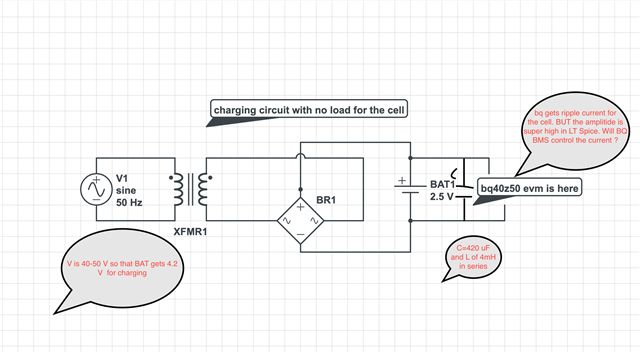
I have an ac supply (3.15 A is maximum current it can give) and a transformer (step down) with bridge rectifier to make the 100 Hz voltage of 4.2 V to charge a single cell. I have a capacitor to smooth out a bit and a resistance of 10 ohms.

on the other side, on the LT spice model, it shows that for such a circuit the current will be super high because the cell resistance is very low. I made this LT spice model starting from the voltage I get on the input of the rectifier (5.8 V sinusoidal 50 Hz signal meaning 5.8*0.707 = 4.10 V RMS) with a cell and capacitor. The current is super high in computer model.

Do you think that I can feed this output from the rectifier (with a capacitor in parallel and an inductor in series) as the power supply in place of a DC power supply to Pack + and Pack - pins for a 1 cell (1s) configuration ?

Actually, AC supply limits the current to 3.15 A. But still I fear if I blow the fuse of my AC supply if I actually connect a cell.

And also, I may damage the bq40z50 evm along with it. As the current will first go to BQ board. 

Will somehow BQ limits the current going to the cell by default ? If not,  do TI has a current limiter circuit that I can buy ?

Regards,

Moonmoon

  • Hi Moonmoon,

    Do you have a schematic we can review.

    Thanks,

    Nick

  •   

    Hello, 

    Sorry for the late reply. 

    Here is the charging circuit. Here I want to feed the output from bridge rectifier as the charging voltage and current for my cell connected to BQ40Z50EVM. But LT spice shows high current (cell has very less resistance like a short circuit for the voltage source) Can BQ BMS control the current flowing from my supply? 

  • Hi Moonmoon,

    bq40Z50 has overcurrent protection, which will turn the charge FET off when triggered, but it cannot control the current value. For controlling the current, you need a charger to work with the gauge, you can choose one on this page www.ti.com/.../products.html

  • Hello Mr. Rashid,

    Can you give me a PDF which explains in detail that how bq40z50 calculate SOC and SOH (DCIR based, I think) in each cycle ? Can I provide email ID here ?

    I have 1 cell configuration. But I really don´t undersatnd the meaning of mΩ values from cell0_Ra, cell1_Ra.... cell2_Ra, cell3_Ra there are lot of values on this data memory. Also, R_a1x.....R_a3x have values in mΩ Does BQ use these values to calculate the impedance at DSG mode in every cycle an updates it? What are the meaning of these values because I didn´t input. They are from cell chemistry flash. 

    Which register corresponds to the impedance at the DSG mode?I have enabled the IR mode because ITEN=1 Where is impedance reflected for each cycle? Please confirm. 

    one last question, does the register ´´current ´´ and ´´charging current´´ don't mean the same ? I see in the graph, ´´charging current´´ is 2000 mA and ´´current is 341 mA

    Why is there a difference in the meaning? Does ´´charging current´´ mean maximum current ? I have not edited any current tabs in memory.

    Regards,

    Moonmoon

  • Hi Moonmoon,

    You can refer to app note SLUA364B and bq40z50 Technical Reference Manuel for SOC and SOH updates.

    Ra values are the internal resistance of the cell, they are included in Chem ID, and are updated in the impedance track algorithm, you should not change them manually.

    Current is the current being sensed by sense resistor, charging current is advised charging current, which is used to inform a host or a charger. 

  • Hello Mr. Rashid,

    Just one more query here. Let say my bqstudio updates SOC (for example 90%) along with external LEDs on the board 4 steady and last one blinks (as expected) but if by any chance a connection is loose between the cell and power supply. I again restart the charging, but this time BQ studio shows 0% SOC with 4100 mV on the dashboard. Why does this happen ? mV are correct but SOC is incorrect completely. Also, one LED blinks meaning SOC very low. How to fix this? 

    Regards,

    Moonmoon

  • Hi Moonmoon,

    Did you mean the charger is loose or the cells to the board connection is loose? Did you do learning cycle?

  • Yes I did the learning cycle. I did not automate the process. I was removing the charger and connecting the resistors path on pack pins. That time I saw that my connection is lost with the bqStudio.  Because of this, I hooked up the charger again and removed the resistor connection which made connection again. That time SOC shown was 0% which was really strange with HV flag=1 This clearly means dashboard was wrong whereas EVM knew that cell voltage is in HV charging status. But this problem was cleared out when I removed the charger and connected it once again. 

    Today I have a separate issue. My update status is 0e. 

    Yesterday I did one CHG-DSG cycle. I expected my cycle count to increase from 13 to 14. But I saw that cycle count did not update. Also in Data memory > State > Qmax cycle count is ZERO I think it is wrong. Qmax of cell 1 is 2917 mAh which is quite high than 2600 mAh design capacity. I learnt from a TI video that Qmax is little bit higher than Design capacity but mine is even higher I suppose.

    1) Can you please tell me why is Qmax cycle count is still zero? ?

    2) why is Qmax is unusually higher ? ?

    3) Which register can I log to see internal temperature of my cell ? ?

  • I see that Qmax cycle count and cycle count are both 4 for my other bq40z50 evm but not for this evm. I have 4 bq40z50 EVMs with me.

    One EVM BQ1 I have blown I think because it doesn't communicate at all. BUT SHOWS CELL VOLTAGE AT BAT PINS AND SUPPLY VOLTAGE AT PACK PINS CORRECTLY (Can you advise me to fix it ?)

    BQ2 has run 4 cycles and cycle count is perfectly updating along with Qmax cycle counts. (both are same) (cycling with DC)

    BQ3 has run almost 15 cycles but does not update cycle count and also does not update Qmax cycle count. (CHG with 500 mA ripple current with high % ripples)

    BQ4 is reserved for other chemistry (NCA). Above I used NMC cells

    I am working with only one EV2400 SMB so everytime I have to hook it up for the other BQ1....4 That is a problem rigth now. But otherwise any suggestions for BQ1 and BQ3 ?

  • Hi Moonmoon,

    If the device is not communicating with bqStudio, it is most likely a hardware issue, you have to check one by one to rule out, but if the damage is internal, there is nothing we can do to fix it.

    Can you provide .gg file and a full bqStudio log of charge to full and discharge to empty for further analyze? 

    Best Regards,

    Abraham

  • fullBQ1Cell2NMCatholidaysCC13notupdatingcheck.log

    Here is my log. I have ran multiple cycles but cycle count is always 13... I have run 4 more cycles. Accurately it should be 17 cycles. I have ran cycles without logging too. Please help. Should I reset the BQ and start from scratch?

    Regards,

    Moonmoon

  • Hi Moonmoon,

    Please upload .gg file corresponding to this log also.

  • How can I get the .gg file ?

  • Hi,

    Open bqStudio-> Data Memory-> Export-> Export

  • Sorry  actually I am learning a new chemistry from yesterday and it is in seal condition that is why I cannot send you .gg file but I  wrote parameters in the data flash from the datasheet and set the cycle count percentage as 90 % and after few cycles 70% when I observed that cycle count is not increasing. But still it didn't.

    Can the reason be that I automated the process with the help of Arduino and a relay and read the voltage and switch the relays to charge and discharge circuits?

    My discharge and charge paths are always there. 

    I wanted to use bq40z50 evm as a cycler and see cycle count and SOH prediction. But it is still not happening. So, I thought to start from scratch and learn the chemistry again.

    Can you advice me what to do in this case (automatic cycler and switching to chg/dsg circuit) ?

    If I do it manually, then it is really hard for me to see ageing. Please suggest. My FC bit is set then only the relay switched. But REST bit is not set.. REST bit takes a lot of time.

    Can cycle count counter bypass this REST time and increase the cycle count? I think cycle count also takes REST bit as a qualifier to increase ?

  • Hi Moonmoon,

    Automating the process won't be an issue as long as the gauge is observing a valid charge and discharge, can you try to set the CCT bit in IT Gauging Configuration register, so that FullChargeCapacity() is used instead of Design Capacity for the cycle count percentage? 

  • Hello Mr. Rashid,

    Here is my .ggcsv file and logsLCCell1_25R_BQ4_allparametersflashed.log for learned gaugeBQ4_Cell1_25R_learnedbms_updatestatus06.gg.csvBQ4_Cell1_25R_CCCVlearningcycle.gg.csv

    Accurately my cycle count should be 3 in this. But it is 3. LFP_RELAX is set but CCT bit was not set. Anyways I am running another cycle which is CC=4 actually but I hope for CC=3 as previous update was unsuccessful.

    Pl note: that even if max error is 1% SOH is 76% in just 2 cycles! It is not a satisfactory number for NCA chemistry.. What things could have caused it ? 

    Regards,

    Moonmoon

  • Hi Moonmoon,

    CC = 2 is correct according to your data, since it increases by 1 when 90% of FCC is passed by. Please follow SLUA903 for standard learning cycle procedure,  one more thing is time interval in your log is too large, it is hard to see the changes, you can change it to 5 ~ 10 s.

    SOH is changing because FCC is changing rapidly in your log, but it is hard to see the reason because of time interval in your log.

  • Hello Mr. Rashid,

    While using BQ40Z50 evm as a cycler, I found that FCC is as less as 1876 in the register and the SOH is 84 or 86 just after few cycles. My Li-ion cell is completely new. 18650 25R 2500 mAh cell. I wanted to characterize the cell using BQ40Z50 EVM. After the logs I ran 10 cycles with a dedicated cycler which shows the following:-

    Cycles (Charged with 1.25A rest 5 mins discharged with 1.25A rest 5 mins)

    Capacity out mAh

    1

    2534

    2

    2500

    3

    2498

    4

    2497

    5

    2497

    6

    2493

    7

    2492

    8

    2491

    9

    2489

    10

    2485

    At the same time BQ40Z50 EVM shows me 84 SOH and FCC of 1846 or 1920 etc.

    Pls note: I have given 1 hour delay time before relay pins switch to either modes of operation (i.e., charge and discharge) This means relay does not switch as soon as Arduino MC sees 4170 mV, rather it waits for 1 hour. This means in this time the charging( discharge) is still running. So it is not like charge is not going in. I cannot think of  a cause about why the reading of a dedicated cycler and BQ40z50 EVM differ? Please help.

    Should't BQ40Z50 BMS be most accurate as compared to a cycler (skyrc mc3000) ? I am pretty sure I have done some mistake in either flash parameters etc. 

    Although REST bit is not set in the BQ Studio. 

    On the other hand the Sky RC cycler had only 5 mins to switch operation.

    I am uploading BQ logs. Please tell me do I have bad parameters that cause it ? I am anxious of the situation because I cannot move on with my thesis topic. I am doing thesis and it is crucial for me to know the problems in parameters or anything else.

    What values I should believe ?

    When I learned the fuel gauge, Qmax went to 2556 which is 56 higher than 2500 mAh. Then why it became 1876 mAh in just few cycles. 

    I have tried changing the cell to other fresh cell of same chemistry on the learned BQ EVM. Still it doesn not reflect correct value. It is evident that cell is not the problem. 

    LOGS

     0131.BQ4_Cell1_CHECK_SOH_FCC_REMCAP_Qmax_changeornot.log1602.LCCell1_25R_BQ4_allparametersflashed.log

    With Regards,

    Moonmoon Pati

  • Hello,

    The SOH is based on the Qmax and Ra table, since the SOH is jumping during discharge the Ra table may be affecting the SOH. Did you change anything after the learning cycle in the dataflash?

    FCC is based on conditions of the batteries, if it's warm you may get higher capacity than expected.

    Sincerely,

    Wyatt Keller