This thread has been locked.

If you have a related question, please click the "Ask a related question" button in the top right corner. The newly created question will be automatically linked to this question.

TPS659037: Device SMPS not.powering up. Is there a shorting?

Part Number: TPS659037
Other Parts Discussed in Thread: AM5718,

We are facing peculiar situation and need your help on TPS6590377ZWSR.

In our custom Card, the resistance between VMAIN & GND is 6 Ohm while cold testing in all 4 boards, clearly expressing shorting in the board. Even after checking all the orientation of devices and capacitors, the resistance was still 6 Ohm in all the boards.

So we decided to give power to VMAIN section at 5V with current limit of 100mA. The board was powered up, but due to current limit set at the power supply, voltage was 1.2 V instead of 5V Input. We slowly increased the current limit to 200mA and eventually took to 400mA, and it resolved all the shorting and board was taking 20mA current after powering up and all the shorting seems to have vanished. This happened on 2 boards. Rest 2 boards, we haven't turned on yet.

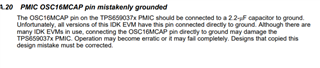
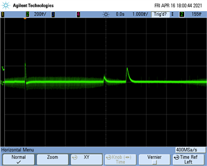
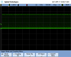
After that we were able to power up the LDO of this device but SMPS are not powering up. Voltage level at SMPS9 is coming at 800mA on both the boards. Rest of the SMPS seems off.

We have cross verified the schematic with the evaluation boards and everything seems to be fine as per custom schematic. But we are still unable to power up SMPS.

Kindly help resolve this issue. Is this due to 6 E at VMAIN during cold testing?

The custom board schematic is almost same as AM5718IDK SD with some modifications done to accomodate our application.

PS: We are planning to change the device TPS6590377ZWSR to TPS6590379ZWSR on one of the boards as last resort as it is a BGA package.

  • Hello,

    What is the test result at room temperature of 25C? What is the resistance between supply and GND at 25C ambient? at what cold temperature you measure 6 Ohms between the supply voltage and the ground? Have you tried it at high temperature?

    Regards 

  • The 6 Ohm resistance measured at ambient temperature of 25 C. How is it related?

    We haven't tried at high temperatures. Cold testing means, devices not powered on and resistance measured between supply and ground at ambient room temperature.

  • Hello,

    I'm thinking if the low resistance is due to moisture at low temperature. This is why I asked to check it at high temperature. Did you have a chance to measure the resistance at high temp?

    How many parts have you tested and how many failure?

    Regards

  • Hi Sir,

    We haven't measured the resistance at low temperatures. We have tested 4 parts and there are all 4 failures. 

    We have even replaced this device with TPS6590379ZWSR, SMPS output is still not coming, but all LDOs are OK.

    What could be the issue? Moisture isn't an issue, I guess. What do we need to do? All our prototype boards are stuck since last 2 weeks. Request you to accord priority to this. 

  • Hello,

    I believe there is design issue because all 4 parts revealed the same issue. would you please send the schematics? Either post it here or you can send it offline.

    Regards

  • The schematic is same as IDK5718 (https://www.ti.com/lit/zip/sprr242) minus U62, U86, U79 and its associated components. Only 2 pages of custom board schematic regarding to this device is attached here. Kindly note that R659 is DNM in the schematic. U2-8 is 5V input to this board.

    L1 was removed so as to isolate VMAIN_2. The resistance was 6 Ohm during cold testing, and is opened by powering on the board with current limit of 500 mA. After that all the shorting was removed automatically, we don't know why. All LDO output is coming, but SMPS are not, except SMPS9 is 1.4V and device is turning off. We then removed R36 & mounted R37 to keep it on. Still SMPSes are not powering up, except SMPS9 which is 1.4V instead of required 3.3V.

    Kindly DM me so as to enable me to share more information, if you need the same. After you study the schematic, kindly delete the same at your end.

    P4-P5.pdf

    Please let me know of any design issues, if any.

    Regards.

  • Hello Dhingra,

    I was looking at IDK5718 design and there is some issue at the crystal oscillator. The max capacitor value C25/C26 should be 10pF (C14/C15 in your design). Also if the crystal is used the OSC16MCAP should have 2.2uF decoupling cap. But this does not explain the low input resistance.

    I can see there are polarized capacitors at the input. Please make sure they are not reversed in the board. Did you measure VMAIN voltage at TP3? It should be higher than 3.15V.

    Regards

  • Hi Mahmoud,

    We have double checked the polarity of capacitors, it is not reversed in the board. Vmain is 5V. It was fluctuating due to input voltage dropping to 3.15V, thereby the supervisory ic generating the reset. We removed the supervisory ic, pulled up the input reset line and the input stopped fluctuating and is stable now. Apparantly, the reset was generated due to voltage drop at input/output of TPS device, due to which we removed the supervisory circuit. Can you explain this behaviour? It is not there in IDK board.

    We have also removed all the decoupling capacitors at the input, still we are unable to get the SMPS up and running.

    Low input resistance of 6 Ohm goes away once we power on the board with current limit of 500mA at 5V first time only (one time). Why is this happening? Afterwards on restarting the board, we get the LDOs output but not SMPS and the shorting at the input is gone.

    Do the OSC decoupling capacitors have any relation to SMPS output not coming out with the above behaviours?

    Is my design ok as per schematic studied by you except the osc decoupling capacitors value?

    Regards.

  • Hi Dhingra,

    Your circuit looks OK but please make sure the layout is good as well. For first check please bypass the voltage supervisor and connect directly the 5V supply to the PMIC supply pins. And pull up the reset-in directly to the supply. Check the switch nodes SMPSx_SWx using a scope probe at power up.

    Regards

  • Hi Madmoud,

    I've already sent the layout on PM. Request you to kindly check that and let me know.  

    We have already bypassed the voltage supervisor and directly connected the 5V supply to PMIC supply pins and pulled up the reset-in line due to the input voltage fluctuating below 3.5V thereby resetting PMIC device. Removal of this circuit fixed this. I suppose this is due to OSC16MCAP pin connected directly to ground.

    We would be trying to mask the C1 pin (OSC16MCAP) today and mount new TPS device to try to isolate it from VCC pin (to rule out 6 Ohm impedance) and keep C1 pin (OSC16MCAP) floating.

    Please ensure to modify the schematic of AM5718IDK (https://www.ti.com/lit/zip/sprr242) so that the same mistake is not repeated by another customer like us. This is going to take lot of resources for us at the moment just to get the custom board running due to this costly mistake in SD at your end.

    By the way, can you please let us know how is the above AM5718IDK board is working when OSC16MCAP is ground? Did you mask this OSC16MCAP pin or? Do we need to program the TPS device over I2C after masking OSC16MCAP pin? 

    Update 0: As advised by you, We have bypassed voltage supervisor and connected directly the 5V Supply to PMIC and also pulled up the reset-in directly to both 5V & 1.8V (VRTC_OUT) one by one. There are no activity at SMPS AND LDOs now.

    Update: I am only able to get LDOVRTC_OUT (1.75V) at this pin after masking OSC16MCAP. Rest of LDO output are not coming. Do we need to program TPS for this modification? 

    Update2: The Oscillator output is not coming at the oscillator capacitors (10 pF), while it is coming in Evaluation Board AM5718IDK. Why? Is there any issue with oscillator circuit?

    Update 3: VBG pin is giving 1.16V output, even before pressing the PWRON button, while as in EVM, it is giving 0.85V only after pressing PWRON button. Why?

    Update 4 (08.04.2021) : We have mounted the Page4 & Page5 (pdf sent earlier) on the bare board with OSC16MCAP ball removed from the TPS IC and no load is connected to the TPS regulator. On first firing of the board without pressing the switch, we got the 16MHz oscillator frequency. On further monitoring, we have observed that there is no 5V output at the PWRON pin/SW1. All the LDOs and SMPS outputs are in rapid slope down. Why is this happening? We have left the GPIO_5 pin open.

    Kindly help us at the earliest. Is it possible for Webex with our team tomorrow during 9am-7pm IST?

    Regards.

  • Issue resolved and discussed during call - this is documented error A.20 on the AM571x EVM user's guide:

  • After masking out OSC16MCAP pin on my board, shorting was removed. With supervisory circuit, the VMAIN voltage was dropping every 76ms, so thereby reset was being given to PMIC every 76ms. After removing supervisory circuit and pulling up reset input to either 1.8V or VMain, input voltage was stable and taking 0.004 A current. But VRTC was 2.2V instead of documented 1.8V. why is it so? Even after pressing POWERON button, No SMPS or LDOs output was coming.

    Kindly guide. Issue still persists. 

    Update 1 (11.04.2021)

    Today we replaced the tps device on one of our boards after baking the device. We were able to get some LDO outputs, 2 LDOs output levels were low. We were not able to get SMPS output. GPIO_7 were pulled up to VRTC.

    After increasing the current limit on our power source to 3A, SMPS output started coming surprisingly but for few milliseconds and shutting down. afterwards we started increasing the current limit to 4A and then 5A, the number of time the output started on was increasing, but it was still in milliseconds. Why is this happening?

    I've sent schematic on Mahmoud's personal email address. Please check and revert as soon as possible about these above behaviours.  

    Regards.

  • Hello,

    Thank you for the update - Mahmoud is OoO today but should be back tomorrow.

    The impact of the current limit is interesting. During start-up, the PMIC input current will be higher than typical operation due to needing to charge the output capacitors quickly. A common issue with bench power supplies is that they are slow to respond to transients. Can you try to add some large bulk capacitance (say 100 uF?) near the PMIC on your board to help the power supply?

    If that does not help, we would need your help to provide oscilloscope shots of the power supply (measured at the PMIC input cap), VRTC, and then the rest of the rails in the power sequence as they boot to see which are affected.

  • Dear Kevin,

    While we will try to send the oscilloscope shots tomorrow, we have seen no output of any of the SMPS, but at LDOs. Some SMPS are turning on during powering up of board, stays for few microseconds, and then shuts down. What could be the reason for this? 

  • Hi Sudhanshu,

    I'm not sure how to understand your post. You mentioned "no output of any of the SMPS" and "Some SMPS are turning on during powering up". These seem to contradict each other.

    My first instinct is that if the SMPS are trying to power up but your power supply cannot provide sufficient current, they may power fault during the boot sequence, causing them to shut down. LDOs require significantly less current (and have less output capacitance to charge up) so they would be less likely to be affected. 

  • Hi Kevin,

    Glad to let you know that we have successfully powered up all the SMPS after setting the input voltage at 5v(already) and current limit was increased from 500mA to 5A. The output started coming from 3A itself, but were fluctuating a lot and our AM5718 was heating a lot.

    We have then tried to isolate the SMPS outputs one by one. When we isolated VSMPS7 by removing R254, the outputs stopped fluctuating. The current reading was 0.5A on the power supply. However the voltage at VSMPS7 was 5V (because of no feedback VDD_CORE??). But now there is no output at VSMPS6 (VDD_GPU). Rest all SMPSes and LDOs are working fine.

    Now we tried to give VDD_CORE voltage from the external power supply at R254-2. The current taken by VDD_CORE was 100 mA. This indicates that the current is well within the VSMPS7's rating of 2A. VSMPS6 output was still absent and VSMPS7 output from device was 5V (even though VDD_CORE voltage was 1.15 V going into SMPS7_FDBK from this external power supply. Why is it so?

    We also tried  to give VDD_CORE voltage from another board which has only TPS659037 mounted with no load (from SMPS7). The behaviour was same as above. VSMPS6 is still absent.

    Can you please explain this behaviour?

    In another 2 PCBs TPS is still not booting up, only LDOVRTC_OUT was coming, rest all  LDOs and SMPSes outputs were absent. In one of this PCB, VBG is 1.21 V, instead of 0.83V as per datasheet. Does this indicate to something? Second PCB doesn't output VBG even. PWRON is 5V on all the above 3 PCBs. The output on 2 PCBs were not coming even after setting current limit to 5A.

    Kindly guide what to do next for all the three faults on these boards?

  • Hello,

    Given that all of your boards are behaving differently, this sounds like a soldering issue. Were these boards professionally built? We have seen a lot of issues with hand soldering rather than reflow ovens due to the number of pins.

    To confirm, all this is happening with the OSC16MCAP fix implemented? 

    You mentioned at the top you are using TPS6590377ZWSR - this is the old revision. TPS6590379ZWSR is recommended for new designs (based on https://www.ti.com/lit/pdf/sliu011) - I don't think it's related, but just a note for you.

    Going back to your boards, I cannot provide much guidance if you have not taken and analyzed your power up oscilloscope shots. Without those, everything is guessing at best.

    1. This sounds like solder short or EOS - can you check resistance between SMPS7_IN and SMPS7_SW?

    2. VBG > expected might mean a leakage - do you have any power supply enabled before the VCC1 to the PMIC?

    3. PWRON being 5V doesn't do anything by itself - are you using a pushbutton? If not, POWERHOLD is generally the power on condition. But if VBG isn't coming up, nothing will do anything. Scope shots of it trying to start up might indicate something, or again it could be a solder bridge.

  • Hi Kevin,

    These are machine soldered and the boards are professionally built. Yes, these are happening with OSC16MCAP fix implemented with ball C1 not soldered (removed the ball from device, and soldered on PCB). Xray is coming ok. We were initially using TPS6590377ZWSR and we have now started to use TPS6590379ZWSR,but same issue.

    We firstly tried using pushbutton using SMPS9, then decided to use VRTC (1.8V) at POWERHOLD to switch on the board as soon as power is given.

    NOW, coming back to the board, we have removed the TPS device from one of the boards, and mounted a new TPS IC (TPS6590379ZWSR ) after baking both custom board and IC and applied 5V power. All the LDOs were turned on along with VBG at 0.83V but SMPS were not turning on. After cycling the power (after cleaning the board with ISO), LDO outputs were changed to 3.6V instead of 3.3V, same happened with other outputs which were elevated. VBG was now 1.2V. Now, LDO9 was not coming, not sure if it was ok at first power on.

    We then decided to remove all the output inductors and cycle the power supply. All the SMPS output is now at 5V (because there is no feedback voltage being fed). We then decided to follow the power sequence given at figure 9 of user's guide (https://www.ti.com/lit/pdf/sliu011) by mounting inductors one by one and cycle  the supply without following the timing as per sequencing at the moment. Then surprisingly all the LDOs were OK except LDO9. VBG is back to 0.83 V.

    Now power sequence is being tracked from this point on without checking the timing between power sequencing (yet).

    1.LDO2-Ok

    2. LDO9-Not Ok (Waveform attached below)

    FYI: LDO9 is not being used on the custom board. The resistor at output of LDO9 is DNM, and VDD_RTC is being fed to AM5718 instead. The circuit is basically same as IDK5718 EVM.

    3. LDOLN-Ok

    4. Mounted inductor at SMPS3 and cycled the supply

    SMPS3-Ok

    5. GPIO_2-Not going high

    Removed the pull down resistor, still not going high to VSYS as per power sequencing.

    6. Then mounted inductor at SMPS7, and cycled the supply.

    SMPS7-Ok.

    We plan to test further tomorrow by mounting inductors one by one.

    What could be the issue regarding LDO9 & GPIO_2? Why aren't they going up?

    Rest of the outputs were staying on. Rest of the SMPS outputs which dont have inductors and therefore no feedback path, were staying on at 5V.

    I will update about rest of the test tomorrow. If you need any more information in the meanwhile, please let me know.

    Update1 (17.04.2021, 9:52 AM) : When the SMPS1_2 inductors were mounted, thereby providing supply to VDD_MPU and feedback path of TPS and power supply turned on, the input current of external power supply starts fluctuating and there is no output of any of SMPS (not even 5V, whose inductors are still not mounted). Is this due to the Sitara AM5718 other supply absent or is the reason something else?

  • Hello,

    Thank you for updates on debug status of your board. LDO9 failing to power up definitely seems like a good place to start on the latest board, though it sounds like it was working, then the board was cleaned, and it stopped working, which suggests a mechanical failure.

    Next step would be checking the LDO input, LDO output, VBG, and LDOVRTC_OUT all in the same scope shot to understand if there is some dependency between them - for example if the VMAIN signal is dropping while LDO is trying to turn. Another variant could include LDO2 as the trigger.

    Is the layout similar to the AM571x IDK as well? Certainly the schematic from PMIC perspective seems an exact copy.

  • Update 2 (17:04;2021, 10:33AM): Pls find attached SMPS1_2 output on scope as below. The voltage at this smps should be 1.15V while it is 2.5V at this SMPS. Why is it so? This is also happening on some other SMPS on some other board. We isolated SMPS1_2 by removing inductor at its output, and connected to other SMPS output having same voltage output and it's working fine without any power sequencing though.

    Also after mounting SMPS9 inductor giving V3_3D and recycling the board, it outputs 5V instead of 3.3V. This is puzzling again. Lot of different issues on different board. Kindly guide. It's been a month, we have not been able to power up our board.

    Pls send me your email address, so that I can send you the layout. Everything is working fine on TPS mounted on bare board though, without AM5718 mounted.

    Also pls let us know if we leave out the non working SMPS, and connect the voltage rails of that SMPS to some other SMPS without taking in consideration the power sequencing of AM5718 because the concerned SMPS isn't booting as demonstrated in graph above, would it boot fine or is power sequencing compulsary? Would we be able to connect to JTAG on CCS it boot via sdcard provided with Am5718 IDK Kit? And what is the basic requirements to boot AM5718?

  • Hello,

    The scope shot looks like a duty cycle of about 1.15/5, though it's too zoomed out to be confident. This would suggest the output is properly regulating - are you confident you are probing the correct point and that your measurement equipment is up to date and calibrated? Or maybe are both SMPS1 and SMPS2 swithching? If so, you'd need to look at both waveforms. 

    Since problems are not consistent and appear and disappear, this points to board assembly issues. Unfortunately I won't be much help there. The other option is EOS damage - if proper lab technique isn't being followed (ESD safe surfaces, ESD wrist straps, etc), the part can be easily damaged by static electricity and will display a wide variety of issues. 

    Once you can get a consistent behavior, the debug can progress - until then I'm not sure what we can do. It seems like a new behavior in every post.

    I will send you a message - we should be able to share sch/layout via E2E. 

    For the AM57x, my understanding is that the sequence is important for long term reliability at a minimum, but I can't confidently say whether any specific sequence might cause damage. 

  • Thank you for sending over schematic and layout. I believe Mahmoud already did a schematic review but I did a quick double check and didn't observe anything beyond OSC16MCAP pin. Layout review from PDFs is not really possible, but I did at least check the converter input capacitor placements and they seemed OK.

    How many boards total do you have and what is the distribution of failure modes?

  • Dear Kevin,

    We have total of 4 boards and there are different failures in each one of them. In some board, all or 1-2 smps outputs are not coming, in some boards, 1-2 smps outputs are fluctuating which I have already told you above, in some boards 1-2 LDO output are not comnig or none is coming. In some boards VBG is not Ok, or is not coming. Note that these are after removing TPS and assembling new TPS devices (with OSC16MCAP balls removed) on these boards. We are unable to infer anything from these failure modes. We have put on hold rest of the boards assembly until we are able to identify the issues. Sending screenshots of LDOs/SMPS seems futile as failures are different in each of the boards.

    So we took a blank board, mounted TPS device with OSC16MCAP ball removed and its associated components are mounted(without sitara AM5718 mounted) and it worked as a charm in the first try and have been working since then without any issues. We gave the smps output from this blank board to fully assembled board on which TPS was working partially (SMPS) and the board started booting up without any issues and we were able to connect AM5718 through JTAG. We are planning to try to mount Sitara on that blank board and test this week.

    Since it's has been a long time we are unable to decipher the issues, it is requested to help us out by conducting either Webex and if required send any TI's Engineer to our site who can help us boot up this TPS and Sitara as soon as possible.

    It is also requested to arrange to send 5 no. samples of TPS659037 and 2 nos of AM5718 as samples as we are almost running out of stock due to frequent replacement of TPS on our boards. 

    I am sending you our address via DM.

    Best Regards,

    Sudhanshu

  • Hi Sudhanshu,

    My apologies, I have started paternity leave today.

    I will assign this to another engineer on my team, but I want to set the right expectations - until you can get boards that are either working or at least failing in a consistent manner from your assembly house, I do not expect us to be able to provide much assistance. I would expect you need to work with them to find root cause for these discrepancies. Based on your experimentation it seems like the PMIC + processor is working as expected when manually done by your team.

    I will reach out to local support to see if there is any support they can add.

  • We are able to get TPS powered up on one of the fully assembled PCB, however SMPS6 (VDD_GPU) is shutting down after a brief power on for whose scope is shown as attached. What could be the reason? What do we need to do?

    We have removed all the decoupling capacitors at the output. VDD_GPU is going directly to AM5718 so there is no way to isolate this supply.

    The impedance at this SMPS6 is 200 Ohm. So doesn't indicates a short.

  • Hi Sudhanshu,

    Can you clarify if this scope shot was taken any capacitance on SMPS6? All of the power regulators on TPS6590377 must have output capacitors for proper function. 

    Are the other rails in the power sequence enabling properly? Can you take another scope shot of SMPS45, SMPS6, SMPS8 and LDO3 so we can see what is happening with the power sequence at this point?

    Best regards,

    Layne J