This thread has been locked.

If you have a related question, please click the "Ask a related question" button in the top right corner. The newly created question will be automatically linked to this question.

TPS55288: Webench Power Designer values inconsistent with datasheet, excel calculator needed.

Part Number: TPS55288
Other Parts Discussed in Thread: CSD17578Q3A

I have been doing the design with this buck-boost and found out that Webench Power Designer is giving false values or datasheet equations are not correct.

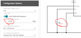
For example when I calculate resistor for 2MHz operation I get value of 9.6kohm and Webench states 9.768k is for ~1MHz. Also what I find annoying with Webench is that even if I manually enter the wanted frequency the tool will automatically change it to whatever it wants.

Could I get an excel calculator that I can refer to and be sure that everything will be correct when I put all the components in to the schematics.

  • Hello Jaakko,

    Please use the excel calculator first to components selection. We will check with WEBENCH team.

  • Hello Jaakko,

    For the Webench issue, it shouldn't happen.  Can you share your Webench design link?

    Gavin

  • It clearly does happen. Also you would need to change the power designer so that user can lock certain components (e.g. inductor) that everytime you want to change voltage for calculation (redesign) it would keep the inductance intact. I haven't yet found an easy way to will the design be stable for the whole 5-20V range because the tool keep changing the components and values automatically.

    The power designer profile for TPS55288 currently cannot be trust to provide correct values for a working design. I need to revert to excel sheet despite the fact I can't verify is the equations in it correct.

  • Hi Jaakko,

    Can you share your application's input/output conditions? We can provide you a excel with selected components.

  • Input will be from 19V power supply. Output should be controllable 5-20V with 5A current.

    We want to use as small 4.7uH inductor as possible. Coilcraft XAL6060-472 would be good candidate with the 5A output current? We are space limited so will prefer ceramic caps over electrolytics and current thought is that we would use one 80-100uF elco on the output in addition to ceramics (4x 22uF or 4x 10uF depending on which gives better eff. capacitance). Switching frequency of 1MHz would be good compromise for this application or can we go lower with the 4.7uH? With 100W output the efficiency is the key though and we are aiming >95% eff. with max power.

  • Hello Jaakko,

    Is it a USB Type C application? 

    I would recommend you follow the 400kHz TPS55288 EVM schematic for reference first.

    When outputting 100W from 19V Vin, the device is working at buck-boost mode, which means the boost stage two FETs are switching. As TPS55288 integrates two Boost FETs, from thermal rise consideration, it's suggested to set the switching frequency at 400kHz.

    When switching frequency is 400kHz, TPS55288 efficiency should meet >95% goal with max power.

  • The buck-boost is used to provide USB-C PD power. 400kHz operation is fine for us. I wanted to verify the selected components (fets, inductor etc.) with Webench Power Designer but that tool is unusable. It keeps changing values and components to whatever it decides is correct.

    For example we would like to use CSD17578Q3A mosfets for both buck high and low side but Power Designer is not allowing to change the low side fet (it's using the same fet always). We would also like to use XAL6060-472 inductor instead of XAL1010 as we have size limitations on the design. XAL6060-472 inductor has ~69% higher saturation current than Ipeak in our operation based on excel calculator which should be enough.

    Could you help on calculating the compensation loop? How to choose the crossover frequency? I cannot use the values directly from 400kHz EVM design as we have less output capacitance (we have 100uF elco and EVM 220uF elco). Should we increase the output capacitance to be able to use higher crossover frequency or is it ok to reduce the crossover frequency to 10kHz or similar?

  • Hello Jaakko,

    This excel calculation tool integrates the bode plot and compensation calculation, which is easy to use for engineers.

    Yes, you can use XAL6060-472 for this application because it has enough saturation current level.

    The MOSFET CSD17578Q3A is a good selection.

    For 100uF Cout, you can use Rcomp=20kohm, Ccomp=10nF, ChF=100pF compensation values first.