This thread has been locked.

If you have a related question, please click the "Ask a related question" button in the top right corner. The newly created question will be automatically linked to this question.

BQ78350-R1A: TS1 has no respond when charger is in soft start condition

Part Number: BQ78350-R1A
Other Parts Discussed in Thread: BQ76930, BQ78350

Hello Sir:

We refer the TIDA00792 document to build our BMS and we have a problem when charger is in soft start condition.

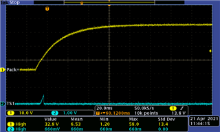
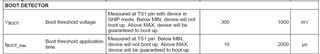
Please refer the waveform of pack+ voltage in our BMS board.

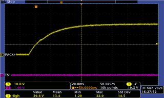
Ch1 is pack+ and Ch3 is TS1, we saw that PACK+ voltage is rising slowly, and TS1 has no responds.

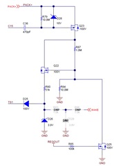
Our schematic shows below.

Please provide recommendations for us how to fix this issue?

Thanks a lot.

  • Hi Statham,

    This circuit comes largely from the examples in this document (BQ769x0 Boot Switch Alternatives): https://www.ti.com/lit/an/slua769/slua769.pdf 

    There are some differences in the TIDA circuit and the tested example in the document. It would be good to review detailed discussion in the document to see if there are changes that are applicable.

    My colleague who wrote this document will be back from vacation tomorrow, so I can ask him to provide any additional suggestions.

    Best regards,

    Matt

  • Hi Matt:

    I checked these circuit but there has no one can help this condition.

    Can you check with your colleague any ideas on this issue?

    Thank you very much for your help and look forward to your reply.

  • Hi Statham,

    From the waveform the charger voltage reaches 20V out of 30V, or 2/3 in about 30ms, so the time constant of your charger seems to be about  30 ms.  In the circuit C36 and R79 have a time-constant of about 4.7 ms.  So likely the charger change slow enough that the FET never comes on to boot the BQ76930.  You can probably do one of 3 things:

    • Change the time constant of the turn on circuit making it longer than that of the charger.  Be sure to give a comfortable margin.  C36 is 470 pF, this can be much larger and still be a common value. 
    • Change the circuit so that Q23 is biased on by voltage: Remove C36 and add a pull down resistor on the Q23 gate.  This will draw current always when the battery is on or the charger is attached, so this is not an attractive solution.
    • Change the circuit to a DC triggered charger voltage: Change C36 to a large resistor.  This would require the charger to go above battery voltage to trigger the circuit.  With a slow charger that may not happen with a fully charged battery so this may not be a workable solution.  The resistor is also a leakage path for charge or discharge, so it should be a large resistor. 

    The first solution is likely best, 10 nF and 10M would give 100 ms, 100 nF and 10M would give 1 s.  Either should hold the gate low while the charger raises the source enough to turn on the FET.

  • Hello Sir:

    We used your recommendations and did some tested.

    Please refer out tested results as below figure.

    1. We used 10nF+5.6Mohm, tested result shows below.

    2. We used 10nF+7.6Mohm, tested result shows below.

    According these two tested results that voltage base did't over 1000mV and time base did over 2000us.

    We think which is not 100% meet datasheet requirement.

    Datasheet means that voltage should be over 1000mV will be guaranteed to boot up.

    Would you please provide recommendations how to increase the voltage?

    Thanks a lot.

  • Hi Statham,

    The circuit is designed to apply the TS1 voltage until the part wakes up.  Once the part is awake with voltage at REGOUT, REGOUT turns Q25 on and the circuit turns off the voltage to TS1.  That is the effect you see in the waveforms. 

    If you would like the TS1 signal to last longer you could implement an analog or digital delay from the REGOUT to the gate of Q25.  You could remove Q25 but then the TS1 pulse would last until Q23 turned off.  If that interferes with a TS1 sample you are using it could put the BQ78350 in a protection state.  Check the settings you are using.

  • Hello Sir:

    Thanks a lot your useful information.

    We changed C36 to 10nF, R79 to 5.6Mohm, parallel a 0.1uF on VGS of Q23.

    And we got this waveform as below.


    Would you please help to check that waveform is OK for every wake up event?

    Thanks a lot.

  • Hi Statham,

    It seems you have found a working solution.  The circuit will only provide a pulse sufficient for the part to wake up.  Once the part is awake it turns off the pulse.   If the part does not turn on Q25 does not turn on and the circuit waits for the part to wake up.