This thread has been locked.

If you have a related question, please click the "Ask a related question" button in the top right corner. The newly created question will be automatically linked to this question.

[FAQ]: Ideal Diode Controller or Linear ORing Controller Gate voltage oscillates at light load or no load

Other Parts Discussed in Thread: TPS2410, LM5051, LM5050-2, LM74700-Q1, LM5050-1, TPS2412

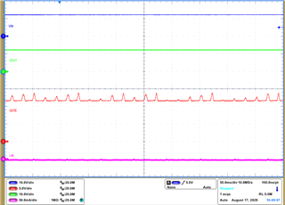
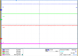
Ideal Diode Controller or Linear ORing Controller Gate voltage oscillates at no load current or light load current causing output voltage to have small ripple.

RELATED PRODUCTS: LM74700-Q1, LM5050-1, LM5050-2, LM5051, TPS2410 and TPS2412

  • Background:
    This is an expected behavior with ideal diode controllers or OR-ing controllers having linear regulation scheme to maintain a very low forward voltage (8mV-22mV) drop. A small minimum load current is required to keep the loop stable and the minimum load current for stable operation depends on the MOSFET and output capacitance used in the circuit. Gate Oscillation at no load current is shown in Figure 1.

    The Linear Regulation control loop has two main poles, with the main pole at the gate of the External FET and the second pole at the output of the FET. First pole is close to origin and the second pole depends on output capacitance and also varies with load current.

    Figure 1: LM74700-Q1 Gate Oscillation at No Load

    LM74700-Q1’s control Loop Gain with location of the poles is shown in Figure 2. As the load current reduces, second pole moves closer to the first pole and this reduces the phase margin. Bode plot for MOSFET DMT6007LFG driving 47uF Capacitance with 10mΩ ESR and load current 100 μA is shown in Figure 3. First Pole is close to origin, second pole is 700 kHz with a zero at 34 kHz due to ESR of output capacitor. Calculated phase margin from the bode plot is 6⁰ at 100 μA.

    Figure 2: Linear Regulation Loop Gain

    Figure 3: Bode Plot: LM74700-Q1 driving N-Channel MOSFET DMT6007LFG

    Solution:

    Impact of Electrolytic Capacitor ESR:
    From the control loop Gain, output capacitance also affects the loop stability, especially ESR of output capacitor impacts stability in a positive way. An electrolytic capacitor with high ESR helps in improving the phase margin and thus reduces the minimum load current required for stable operation. Thus minimum load current required to keep the gate voltage stable is lower with the presence of electrolytic capacitor with ESR.

    For LM74700-Q1, a minimum of 100 μA is required to keep the gate voltage stable and with stable output voltage without ripple. Adding a 120 kΩ resistor from output to GND keeps the load current 100 μA at 12V input voltage. Note that the minimum current of 100 μA adds to the IQ (ON) current and increases the IQ (ON) current.
    Figure 4 shows stable operation with no oscillation in gate voltage after adding 100 μA load current.

    Figure 4: LM74700-Q1 Stable Gate Voltage with 100 μA Load Current

    Stable operation without Electrolytic Capacitor ESR:
    Absence of electrolytic capacitor or presence of large ceramic capacitance other than the minimum 0.1 μF or the 2.2 μF ceramic capacitance recommended in datasheet or evaluation module would increase the minimum load current required for stable operation.
    To be more precise, minimum 1mA is required for stable gate voltage with 2.2uF at the output without electrolytic capacitor. Minimum current required for stable operation reduces with electrolytic capacitor and its high ESR.


    Application with high power MOSFETs:
    As the MOSFET size increases or the RDS (ON) decreases, pole due to GM of the MOSFET occurs at higher frequency. Phase margin from the bode plot needs to recalculated based on MOSFET parameters as the pole can cross the zero due to output capacitance ESR.