This thread has been locked.

If you have a related question, please click the "Ask a related question" button in the top right corner. The newly created question will be automatically linked to this question.

LMZ13608: LMZ13608TZE/NOPB Shorts occur at pins 6 and 7

Part Number: LMZ13608

Hi team,

the customer have a question:
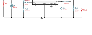
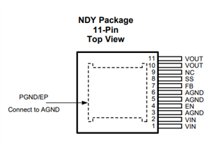
LMZ13608TZE/NOPB.

The product was produced using the circuit diagram and product that you advised me.
Shorts occur at pins 6 and 7.

Please check what is the cause of the short circuit.

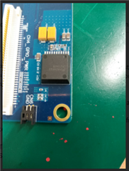
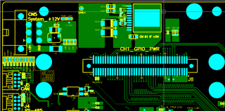
At our factory, we doubt whether the product is defective. :( Is it possible that it is defective? I can send you probme parts samples from my board.

Best regards,

  • Hi,

    What circuit diagram are you referring to? 

    On the LMZ13608 power module, Pin 6 is AGND and Pin 7 is FB. If Pin 6 and Pin 7 are shorted together, then it will result in the output voltage going higher programmed output voltage. 

    Are the samples confirmed to have Pin 6 shorted to Pin 7 straight out of the tape-and-reel? Has customer done continuity check on just the power module IC itself to confirm short or was this observed after customer board power up?

    Regards,

    Jimmy

  • Hi Jimmy,

    thank for your reply.I will add a circuit diagram for you .

    Please analyze it again.

    Thank very much.

    Best regard,

  • Hi,

    Thanks for showing a portion of the schematic. 

    Can you comment on if the Pin 6 to Pin 7 short is on the actual device from tape-and-reel? This will exercise if the device itself has any defects straight from the reel.

    If it is shorted on the board, can you also check to make sure the bottom resistor (Rfbb) is not damaged? If Rfbb is damaged then it is possible that the FB pin is shorted to GND. 

    Regards,

    Jimmy 

  • Hi Jimmy,

    Thank you for your professional answer.

    The customer further questions.please help to analysis.

     I had made boards using all of LMZ13608 that I purchased.

    When I done to make all boards, I tested some of Boards with the board power up. it had something problem.
    So, I tested it without Board power up, It had same proble too.

    That is why, I removed LMZ13608 from the board to test the chip LMZ13608.
    When I tested the LMZ13608, there was a short problem on pins 7 and 8. It has also happend pins 1 and 2.

    I would like to know what is the reason for this problem.
    It could be happen when I doing SMT (Surface Mounting Technology) ?
    Is there any bad conditions to affactive the Pins 1,2,6,7 ?

    Thanks,

    Best regards,

  • Hi,

    Please provide the following items for review:

    1. Full image of schematic and PCB layout with all layers for review.
    2. Actual camera image of the board you are working on so I can check for any solder shorts or component discoloration.

    Pin 1 and Pin 2 are VIN pins so this makes sense why the two pins would be shorted. So far I've read Pin 7/8 shorted and Pin 6/7 shorted. There needs to be further investigation on the unit itself. Please do the following below:

    • Have you tested continuity of several of the new unit straight out of the tape-and-reel? This is easy enough to do with a multi-meter since this is a leaded package with the pins perturbing out of the package. Please verify that the units do not have any shorts before assembly onto your board. 

    These units go through extensive testing and continuity tests prior to being released and public for customers to purchase so there should not be any device level issues. 

    Also I would suggest you order a few LMZ13608EVMs from the TI store to help evaluate this part's functionality.

    Regards,

    Jimmy

  • Hi Jimmy,

    I am sorry, there are some things wrong.
    Shorts 1 and 2 occur, and shorts 6 and 7. Its correct.

    I have already purchased the LMZ13608EVAL and have completed several tests. (order# T01147871)

    The problem occurred after mounting the item on the board.
    Is there any possibility that could occur during the SMT process?
    If than Can I know what conditions it is?
    Because after doing SMT, it had happend.

    I will check the schematic and Full image that you need.

    Thanks

  • Hi,

    I'd like to point you to the visual pin configuration of the power module. Note that Pin 1/2 should be shorted since both pins are VIN designators.

    Pin 6/7 should not be shorted since that would result in the device not regulating properly.


    You did not comment so I'll ask again: Have you tested continuity of several of the new unit straight out of the tape-and-reel? This check is to make sure that the device does not have any shorts before assembly. Again I don't think this will be the case since these parts should have been through extensive testing and continuity test before being sold, but please do this to double confirm.

    Figure 57 shows the proper reflow profile for assembly of this device onto your board. How are you reflowing the device onto your board? If your reflow profile is above the temperature profile there is a possibility of  thermally damaging the part. Please check your reflow profile and comment on how you are reflowing this device onto the board during assembly.

    Please provide full schematic, PCB layout of the board and full image for review of any component discoloration. 

    Regards,

    Jimmy  

  • Hi Jimmy,

    Thanks for your reply.

    Pins 1/2 are all VIN designators, so they must be shorted.
    => I can't understand this sentence. Why should pin 1/2 be shorted?
    Are there any conditions to short pin 1/2?

    I also attached a picture of the whole board and a schematic.

     메인_보드_전원부___210419___LMZ13608TZE .PDF.pdf

    I'm also doing test with new device straight from tape and reel. I will tell you the result.

    Thanks

  • Hi,

    When I said "Note that Pin 1/2 should be shorted since both pins are VIN designators" this means both Pin 1 and Pin 2 are internally connected and would appear as a short from continuity measurement. As when you connect this device on your board two pins will share the same VIN plane and effectively be "shorted" together.  

    A few other questions:

    1. Do you have several boards that show the issue of Pin 6 to Pin 7 short?
    2. Do you have any board that actually turns on properly with a regulated output voltage?
    3. Please get back to me on the tape-and-reel test so I can rule out potential device issues before assembly.
    4. Can you provide the PCB layout for review? The pdf schematic looks okay. 
  • Hi Jimmy,

    Thanks for your reply.
    1.Do you have several boards that show the issue of Pin 6 to Pin 7 short?
    - There were around 150 pcs of chips problem of Pin 6/7.

    2.Do you have any board that actually turns on properly with a regulated output voltage?
    - Excluding parts that have some chip problems. Most of the boards are working fine.

    3.Please get back to me on the tape-and-reel test so I can rule out potential device issues before assembly.
    - The order Qty was 7760 and I used it 7500.
    - I have done tape and reel Tests with left 100pcs, It was no short problem.

    4.Can you provide the PCB layout for review? The pdf schematic looks okay.
    - I have attached the some files.


    Thanks

  • Hi,

    150pc with short between Pin 6 and Pin 7 is a lot and definitely out of ordinary. 

    Can you also provide the following information:

    1. What is the tape-and-reel package information (lot code, date code, etc.)? It should be on the tape-and-reel package
    2. The 150pc units that were discovered to have Pin 6 to Pin 7 short was found straight during the tape-and-reel test correct? This means the units you discovered already had the shorts straight from the package and not after assembly. 
    3. Can you try baking the 150pc units for at least 24hrs? My thought here is perhaps inducing heat to the device would remove any moisture that is trapped in the part and possible clear the unit of the short. 

    I believe you should also initiate a customer return to TI per the following link. I would like to get these suspect units to have it tested and reviewed internally at TI.

    Regards,

    Jimmy 

  • Hi Jimmy,

    The customer reply that:

    I bought 7,760 pieces from TI.com 03/11
    order # T01174694 3,760pcs
    order # T01174691 4,000pcs
    7,600 pcs I had been on the board alreday.

    I tested 20pcs tapes and reels on a new reel when I got it.
    After making the board with 7,600 pieces.
    Some LMZ13608TZE had problem pin 6/7. It was around for 150pcs.

    Also I Tested with 100 unused. It was okay.

    So I think something is wrong when I was doing SMT.
    I need your opinion, what mistakes did I make? Or if there is a problem on the part LMZ13608TZE ?
    I need to know what is the reason.

    Also I can send you a sample from 150pcs with problem.

    Thanks

  • Hi,

    Thank you for providing the new information. It sounds like the device does not have issues during tape-and-reel testing. It only has the issue after assembly onto customer board. 

    Please have the customer refer to Figure 27 for proper solder reflow profile. If the customer is following a different reflow profile that is above the peak temperature of 245degC, there is a possibility of the device having internal damage due to thermal stress during SMT assembly.

    Also refer to the design summary of this device.   

    For customer returns, please follow the instructions in this link to have samples returned to TI for additional review. 

    Regards,

    Jimmy 

  • Hi,

    Can I get an update on this? All our previous discussion is pointing to the device having shorting issues during SMT assembly/reflow process.

    Regards,

    Jimmy 

  • Hi,

    Thank you for tracking the case. I've been waiting for feedback from customers. I'll share with you any progress.

    Best regards,

  • Hi,

    The customer feedback:

    For the return.
    Could you test the problem samples of Pins 6/7 if I send you?

    Does it need extra cost? if it needs can I know the price of cost with period of Test ?

    Thanks

  • Hi,

    I would suggest following the instructions on the customer return link (https://www.ti.com/support-quality/additional-information/customer-returns.html). I don't think it would cost anything additional. 

    Did your customer have a chance to comment on their solder reflow profile? Are they violating any peak temperature settings that could be damaging the device? Again I'd like to mention that all the previous discussions have hinted that the issue may be SMT assembly related or potential thermal stress on the part. 

    Regards,

    Jimmy