This thread has been locked.

If you have a related question, please click the "Ask a related question" button in the top right corner. The newly created question will be automatically linked to this question.

BQ25730: BQ25730 Charging, OTG mode, BATFET operation

Part Number: BQ25730
Other Parts Discussed in Thread: BQ25703A

Hi,
Let me apologize first, as it is going to be a long questionnaire.

Planning to use BQ5730 as a 3S1P/3S2P charger.
It is not a USB/PD application, but purely a battery charging and discharging application- also enquiring if we can hack the OTG/FRS feature of the PD 3.0 it supports.

  1. We are trying to charge and discharge through the same VBUS. I understand that BQ25730 can swap its role from a power sink to a power source as soon as the external DC adapter-in loses its power when it is in FRS mode. I also understand that the output voltage and current at VBUS will be as per the value written into the corresponding registers of BQ25730. Our application is around 12V (can be between 12V & 13V) My first question is that if BQ25730 can generate such a voltage (say, between 12V&13V) at its VBUS from a 3S battery (12.6V)?  or, is it limited to typical 5V/9V/15V/20V?

  2. I see that BQ25703A and  BQ25730 both incorporate OTG support. BQ25703A starts sourcing at VBUS in 10ms after the conditions (section 8.3.3 in DS) are met, but BQ25730 takes 15ms to start sourcing at VBUS after the listed conditions (section 9.3.9 in DS) are met. Only BQ25730 supports Fast Role Swap- Isn't it contradictory that the device without FRS sources quicker? what advantage do we get with FRS-enabled BQ25730 in the context of higher sourcing delay?

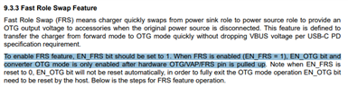
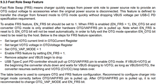
  3. As I mentioned before, this application has nothing to do with USB or USB power delivery, hence no PD controllers and CC pins. So in order to utilize FRS or to be in FRS ready mode always, can you please confirm if the below steps taken in design are sufficient?
    a) OTG/VAP/FRS pin permanently set high with a pullup resistor.
    b) Setting target IOTG current limit & VOTG voltage in OTGCurrent Register & OTGVoltage Register respectively by host MCU during initialization.
    c) Writing OTG_VAP_MODE=1b & EN_FRS BIT=1b by host MCU during initialization.
    d) Waiting for the DC-in at VBUS to drop in order to source set voltage at VBUS pin from the battery (in forward mode) / Waiting for DC-in at the VBUS to charge the battery while it is in sinking mode 

  4. Does enabling charge termination by the host, once the battery is full, have any impact on FRS?

  5. This is regarding the charging of Battery- How does BQ25730 stop charging when host tries to terminate charging either by setting CHRG_INHIBIT or by writing zero to charge current()? Is it by turning off BATFET  off? will the VSYS have any impact? will it still drive the load connected to VSYS?

  6. How does the charger charge the battery and at the same time, make sure that the battery is not supplementing the system (discharging) in normal charging mode (no supplementation)? Does the voltage difference before & after BATFET ensure current flow is towards the battery only while it is charging? If that is the case, how does NVDC work when the battery is still charging (as it will still have the same voltage difference, yet have to discharge the battery)?

Thanks and regards
Abin

  • Hi Abin,


    1) Yes, the BQ25730 can output 12-13V at VBUS in OTG mode. The OTG output voltage range is between 3-24 V, with an 8 mV step size.

    2) These are two distinct cases. 10 ms/15 ms is the OTG mode startup time. In this case, VBUS is initially absent (below VVBUS_CONVENZ), and the converter is not switching yet. We are measuring the time between when OTG mode is enabled, and when the VBUS voltage actually ramps up. 

    On the other hand, for FRS, VBUS is initially present, and the converter is already switching. The adapter is then unplugged from VBUS, so FRS activates and quickly swaps the converter from forward mode to OTG mode. If VBUS > VOTG at the beginning, then the converter shuts down and waits for VBUS to drop down to VOTG. Once this happens, the converter resumes switching in order to maintain VBUS at VOTG. This happens very quickly (typically in the hundreds of us, although the exact time depends on how long VBUS takes to drop down to VOTG). FRS is described in more detail in Section 9.3.3 of the datasheet.

    To summarize, FRS is for converter switching in forward mode -> converter switching in OTG mode. On the other hand, the 10 ms/15 ms OTG startup time is for converter not switching -> converter switching in OTG mode.

    3) It is not recommended to change the OTG_VAP_MODE and EN_FRS bits after the OTG/VAP/FRS pin has already been pulled high, as described in Section 9.3.3 of the datasheet. Instead of permanently pulling the OTG/VAP/FRS pin high, please configure the BQ25730's register settings correctly first while the OTG/VAP/FRS pin is low, and then pull the OTG/VAP/FRS pin high.

    4) No, this shouldn't impact FRS. The BQ25730 is still in a power sink role, and it can quickly swap to a power source role when the adapter is disconnected.

    5) When charging is disabled (for example, by setting the CHRG_INHIBIT bit = 1, or setting the ChargeCurrent() register to zero), the BATFET turns off. Using adapter power, the BQ25730 will still power a system load connected at VSYS. If the system load rises and begins to overload the adapter, causing VSYS to fall below VBAT, then the BATFET will turn on again so that the battery can work in supplement mode and discharge to help power the system. This is discussed in Sections 9.3.17 and 9.4.1.1 in the datasheet.

    6) By regulating VSYS above VBAT and monitoring the charge current through the sense resistor, the BQ25730 can make sure that the current flow is into the battery. If the system load rises, causing the device to exceed the IINDPM or VINDPM settings, then the BQ25730 will reduce the charge current in order to prioritize powering the system load. Eventually, if the charge current drops down to zero, then VSYS will start to drop because the adapter is overloaded. The battery will then discharge to supplement the adapter and help power the heavy system load. Similar to 5), I suggest referring to Sections 9.3.17 and 9.4.1.1 for more information.

    Best regards,

    Angelo

  • Hi Angelo,
    A big thanks to you. Appreciate the effort put to give precise information.!
    Just to confirm some very important points concerning us,

    3)

    3) It is not recommended to change the OTG_VAP_MODE and EN_FRS bits after the OTG/VAP/FRS pin has already been pulled high, as described in Section 9.3.3 of the datasheet. Instead of permanently pulling the OTG/VAP/FRS pin high, please configure the BQ25730's register settings correctly first while the OTG/VAP/FRS pin is low, and then pull the OTG/VAP/FRS pin high.
    • OK got it. But is the EN_OTG bit set by-charger itself? The statement gives a notion like that. Moreover, table 9-1 doesn't show the case where OTG/VAP/FRS=1 and EN_FRS BIT =1.


    • Can you please confirm that it is required to set these registers and pull OTG/VAP/FRS=1 only once and it handles multiple cycles of forward mode and OTG role reversal?

    5)

    5) When charging is disabled (for example, by setting the CHRG_INHIBIT bit = 1, or setting the ChargeCurrent() register to zero), the BATFET turns off. Using adapter power, the BQ25730 will still power a system load connected at VSYS. If the system load rises and begins to overload the adapter, causing VSYS to fall below VBAT, then the BATFET will turn on again so that the battery can work in supplement mode and discharge to help power the system. This is discussed in Sections 9.3.17 and 9.4.1.1 in the datasheet.

    Thanks for confirming. 
    Again in 9.4.1.1, it says when BATFET is off, the charger maintains sys Voltage 150mV above VBAT. What is the purpose of that? Anyways BATFET is OFF and it doesn't conduct.

    Much thanks & regards
    Abin

  • Hi Angelo, 

    Any news on my query?

  • Hi Abin,


    3) Please refer to the sequence of steps given in Section 9.3.3. If EN_FRS = 1 and the adapter is removed, and then the OTG/VAP/FRS pin is pulled high, then the EN_OTG bit is set to 1 automatically, and the converter begins switching in OTG mode.


    For FRS, please follow this sequence of steps every time you switch roles from forward mode to OTG mode. In other words, please pull the OTG/VAP/FRS pin low, then set the OTG_VAP_MODE and EN_FRS bits appropriately, and finally pull the OTG/VAP/FRS pin high again when you wish to re-enable FRS next time.


    If possible, I recommend ordering a BQ25730 EVM. The EVM is the best way to evaluate the behavior of the device, and it can also save debugging time later on when you design your own circuit.


    5) The system load has priority and should be powered even when the BATFET is off. I think there are several reasons for regulating VSYS slightly above VBAT (VSYS = VBAT + 150 mV) when charging is disabled. To illustrate this, we can consider some of the alternatives:

    • If VSYS were regulated high above VBAT, then at the moment the user decides to re-enable charging, there will be a large current spike into the battery when the BATFET turns on.
    • If VSYS were regulated below VBAT, then the BATFET's body diode (pointing from BAT towards SYS) may start conducting reverse current. The parasitic body diode can conduct current even when the BATFET is off.

    Best regards,

    Angelo

  • Hi Angelo,

    Thank you very much for clarifying.