This thread has been locked.

If you have a related question, please click the "Ask a related question" button in the top right corner. The newly created question will be automatically linked to this question.

LM5122: Please review the schematic (and one question)

Part Number: LM5122

Hello TI experts,

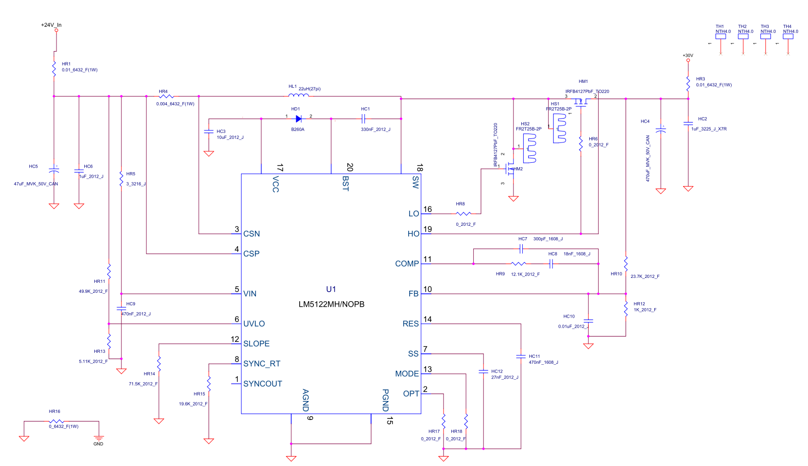
my customer made a sample with LM5122, could you review the schematic?

and I have one question,

what is the maximum current(A) or power(W) of this device?

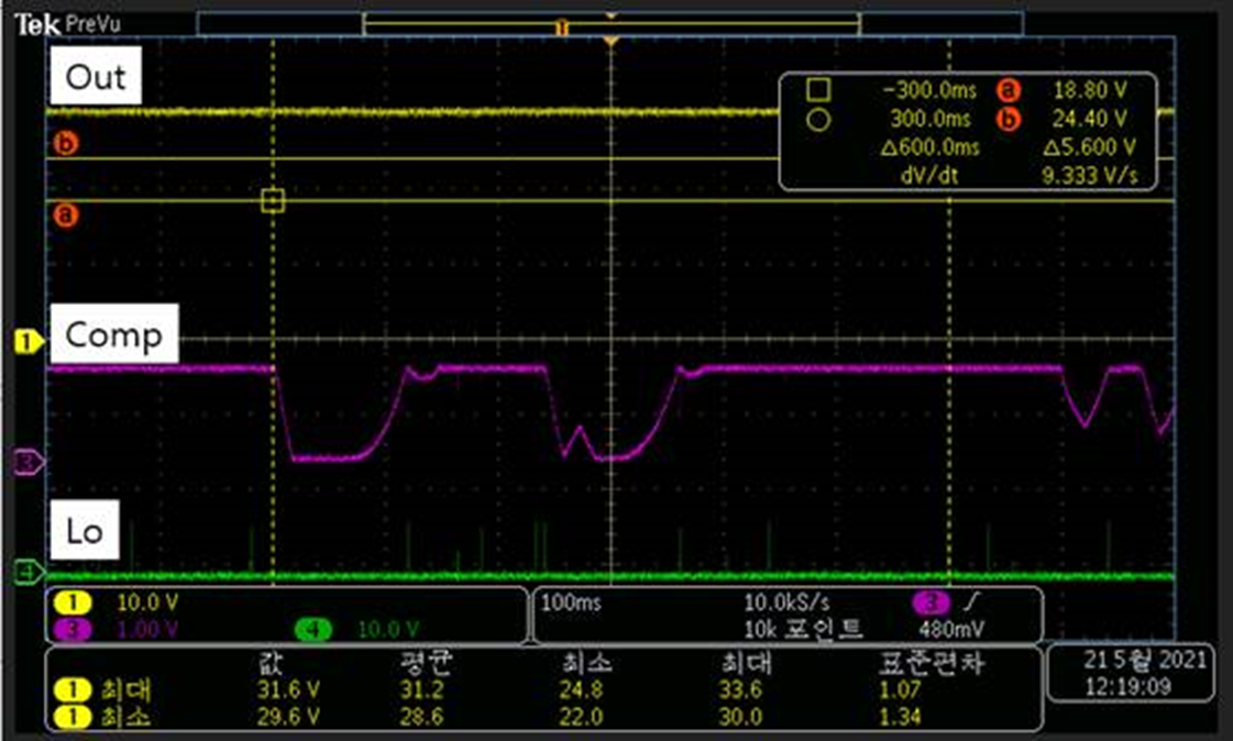
cause sometimes the output is decreased from 30V to 24V, finally the output is same as input.

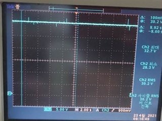
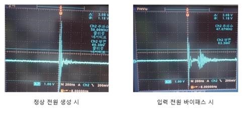
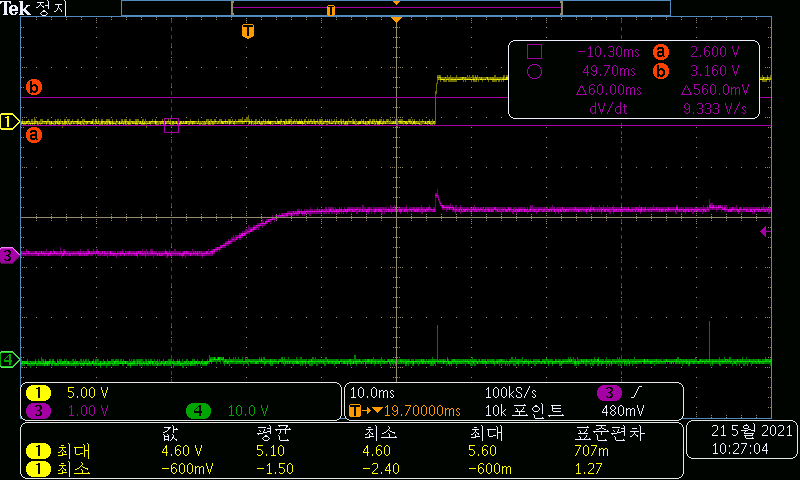
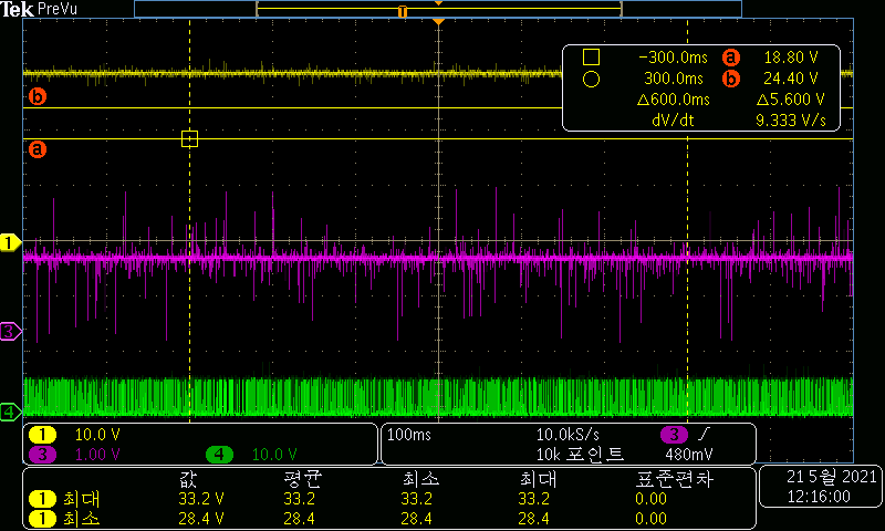
please see the waveform below.

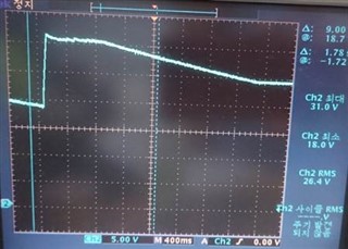
(the sharp rising edge is the power on status.)

and about after 3second, it decreased to 24V.

can you expect the reason of this situation?

Best regards,

Chase

  • Hi Chase,

    Thank you for selecting LM5122.

    I will review the schematic and let you know. For your question, did they check the temperature of the IC when they see the output drop?

    Thanks,

    Yinsong

  • Hi Yinsong,

    Thank you for your support.

    did they check the temperature of the IC when they see the output drop?

     => they did not see anything special about temperature. we think that the power just bypass the IC. and the room temperature was 25℃

    and I will attach the waveform of output when the normal operation.

    please let me know if you need more information about this. Thanks.

    Best regards,

    Chase

  • Hi Chase,

    What is the load when they saw this problem? I'll review the schematic.

    Thanks,

    Yinsong

  • Hi Yinsong,

    current was not an issue at that time. about less than 1A.

    please let me know if you want anything about this. Thanks.

    Best regards,

    Chase

  • Hi Chase,

    Thanks for the confirmation. I'll review the schematic and let you know.

    Thanks,

    Yinsong

  • Hi Chase,

    Some questions.

    1. What are HS1 and HS2? I cannot find the part number online?
    2. What is the part number for HL1? Or saturation current?
    3. What is the part number of HC2? Or voltage rating?
    4. What is the open trace on the right of the HO to HM1 gate trace?
    5. What is the part number of HC1?
    6. The 100nC typ and 150nC max Qg of HM1 is large. HC1 may not be able to hold enough BST voltage. Please check the BST and VCC waveform.

    + Some suggestion:
    1 recommend to add RC filter on the current sense.
    2 recommend to use >120nF SS cap to minimize the overshoot.
    3 usually HC10 is not needed.

    Do they have the waveform that shows both input and output waveform together? It is strange that the input drops before the rise if the input supply is constant.

    Thanks,

    Yinsong

  • HI Yinsong,

    Thank you for your support.

    I requested the information you requested, will send you asap.

    and I have some questions about your suggestions;

    1 recommend to add RC filter on the current sense.

    => could you suggest the values of R & C and exact location of filter?

    2 recommend to use >120nF SS cap to minimize the overshoot.

    => i saw that 47nF cap on SS pin in WEBENCH. could you explain the reason why I increase such high value for SS cap?

    https://webench.ti.com/power-designer/switching-regulator/customize/43?VinMin=23&VinMax=25&O1V=30&O1I=5&base_pn=LM5122&AppType=POWER&Flavor=NA&op_TA=30&origin=pf_panel&lang_chosen=en-US&optfactor=3&Topology=Boost&flavor=NA&VoltageOption=NA

    3 usually HC10 is not needed.

    => I agree with you for this suggestion.

    please check this issue. Thanks.

    Best regards,

    Chase

  • Hi Chase,

    1. Please see the Figure.40 in datasheet for the filter values and positions.

    2. There is no strict rule for SS cap value. One way to help reduce the inrush current to reasonable range: Css=(Iss*Vout*Cout)/Iout.

    Thanks,

    Yinsong

  • Hi Yinsong,

    Here is the answers which i got from my customer ;

    1. What are HS1 and HS2? I cannot find the part number online?

    => They are just heat sync. I think we don't have to think about it.

     2. What is the part number for HL1? Or saturation current?

    => it is toroidal core inductor, 13uH. i will check more for Isat and part number.

    3. What is the part number of HC2? Or voltage rating?

    => it is just MLCC chip capacitor. voltage rating is around 50V.

    4. What is the open trace on the right of the HO to HM1 gate trace?

    => it is just opened, same as not existing.

    5. What is the part number of HC1?

    => it is just MLCC chip capacitor. voltage rating is around 50V.

    6. The 100nC typ and 150nC max Qg of HM1 is large. HC1 may not be able to hold enough BST voltage. Please check the BST and VCC waveform.

    => i attach the waveform of input, output, BST and VCC. they have only one probe, so they cannot captured at the same time.

    LM5122_waveform.pptx

    and I have another request, please let me know if there are any requirements about Isat(HL1), voltage rating (HC1, HC2)

    Best regards,

    Chase

  • Hi Chase,

    Thank you for the information. The 50V voltage rating for HC1 and HC2 should be ok. The HL1 Isat depends on the max load required and the R sense for current limit protection.

    Regarding the waveform, are they under no load condition? Also, it seems the outupt voltage is regulated to ~30V without dropping low?

    Thanks,

    Yinsong

  • Hi Yinsong,

    Thank you for your support.

    Yes, they can see this problem under no load condition.

    and they tested something else, i share about it.

    now they test it with power supply. when they first power the supply on, LM5122 works well.

    but they power the supply down and after 1 or 2 seconds later power on again, the input bypass.

    they tried it several times, it still bypasses.

    and they power down, wait about more than 20 minutes, sometimes it works well, sometimes not.

    I think there are some remaining power in the IC if the time is too short after power down. so it maybe work wrong.

    also they attached waveform of RES pin. they think that there is some problem while restart IC.


    left waveform is in normal situation, right waveform is under problem.

    please let me know if you want to know more about this problem. Thanks.

    Best regsrds,

    Chase

  • Hi Chase,

    Does this issue happen on multiple boards and ICs?

    What is the time scale of the waveform? Is it 200ns?

    In those cases where the Vout drops to Vin, does it ever come back up or not? And I'll need some waveform in those cases to help debug. First, please check if they can get the FB, COMP and LO waveform.

    Thanks,

    Yinsong

  • Hi Yinsong,

    Does this issue happen on multiple boards and ICs?

    => Yes, it happen on multiple ICs.

    What is the time scale of the waveform? Is it 200ns?

    => Yes, time scale is 200ns.

    In those cases where the Vout drops to Vin, does it ever come back up or not?

    => As i said it occurs randomly. and it never come back until I power down the IC and wait about more than 20 minutes.

    if And I'll need some waveform in those cases to help debug. First, please check if they can get the FB, COMP and LO waveform.

    => what moment of those waveforms do you need? the moment that the problem begins? please tell me more about it.

    Best regards,

    Chase

  • Hi Chase,

    Thank you for the answers. I would like to see the waveforms when Vout drops to close to Vin.

    Thanks,

    Yinsong

  • Hi Yinsong,

    Here is the waveforms you requested.

    This is the waveforms right after the power is on.

    This is the waveform which the time is passed by. we could see the comp pin is unstable. is it one of the reason of this problem?

    also I want to know that the ideal waveforms of COMP and LO. can you show it?

    Best regards,

    Chase

  • Hi Chase,

    The COMP should be essentially a DC waveform between around 1 to 3V. So the high level of COMP in the waveform looks ok but it is a problem when it is somehow pulled down to ground. LO should be a constant duty cycle PWM at the given switching frequency.

    In the first waveform, is the yellow one also Vout? Why is is only 5V? And in the second waveform, it seems the Vout is 30V as expected?

    If the COMP is really the issue, please first check the FB voltage and SS voltage.

    Thanks,

    Yinsong

  • Hi Yinsong,

    Sorry for the late reply, the customer was busy because of other issues.

    anyway here is new waveform, Vout / FB / SS.

    customer has a doubt that FB has some noise, the reason of same value of input and output.

    and is there any possibility that the problem of artwork?

    last request, can we discuss this issue through offline? I think E2E is little slow for solve the problem.

    please check these issue, and let me know if you want to know more information about this. Thanks.

    Best regards,

    Chase

  • Hi Chase,

    The 100ms time scale is too large so the FB could really be up and down not noise. Also the SS does not look right. And still, it seems the Vout is good? Isn't it supposed to regulate to 30V?

    You can also reach me and our team through email if you like.

    Thanks,

    Yinsong

  • Hi Yinsong,

    customer captured this shot because they doubted the noise of FB pin. so they captured when LM5122 works normally.

    and you said that it is not a problem.

    how about artwork? is it possible that the matter is from artwork even the schematic itself is good enough?

    and if you tell me your email address and your team's, i will contact you through email as i said.

    Best regards,

    Chase

  • Hi Chase,

    It's hard to tell if it's noise or real drop before zoom-in waveform is presented. The SS here also worth having a closer look. When you say artwork do you mean the soldering and population of the board? I can give a review of the schematic as well.

    I'll add you to my contact.

    Thanks,

    Yinsong

  • Hi Yinsong,

    Thank you for accepting my suggestion.

    let me know you email address, or send me a private message. and we can discuss this matter again.

    Best regards,

    Chase

  • Hi Yinsong,

    I sent you an email about this issue. Please check email. Thanks,

    Best regards,

    Chase

  • Hi Chase,

    I'm sorry but I do not get your email. Could you please send it again?

    Thanks,

    Yinsong