This thread has been locked.

If you have a related question, please click the "Ask a related question" button in the top right corner. The newly created question will be automatically linked to this question.

Problems getting BQ24630 to battery discover and charge at high rates...

Other Parts Discussed in Thread: BQ24620, BQ24630

Hello, I am having problems migrating my design for a 4 cell charger to the BQ24630.  I had initially used the BQ24620 and designed it for a 10Amp charge current.  That board worked great and still does.  However, my customer required the charge rate to be reduced to 5Amps and since the battery capacity is very large, the safety timer would not allow me to use that part any more.  So, I moved the design to the BQ24630 since I saw an E2E answer indicating how to disable the safety timer on that chip, but still allow normal charge termination.  Anyway, I moved all of the design as it was including feedback networks, etc to the new chip (24630).

On this board using the BQ24630, I have a multitude of problems that I need some help with.

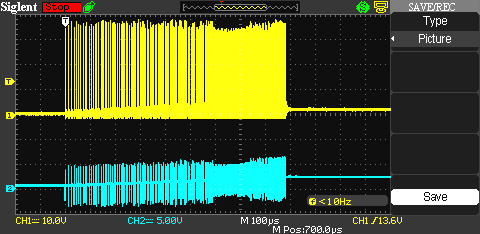
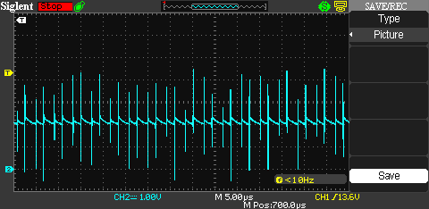
1.  The battery discovery appears to start, with proper looking waveforms, but stops in the middle of the first burst once the output voltage reaches ~2.3V.  I can see the voltage ramp up, but then it just stops and never continues no matter how long I wait.  The old board with the 24620 would do the 0.5 second burst even if the voltage reached the 14.6 volt limit early and would just pulse skip to keep it above the regulated threshold until the 0.5 second and then would begin the discharge cycle as advertised in the datasheet for either part.  This 24630 seems to just stop early and then never continue the remainder of the 0.5 second interval.  I did play around with restarting the power before the output voltage would decay thinking that maybe it was a timeout of some sort.  However, no matter what the output voltage was when power was first applied, the first burst of the battery detection stops immediately when the ~2.3V is reached.  I played around with reducing the output capacitance (I use 2 x 22uF), and removed one of the caps.  This only resulted in the 2.3 volts being reached faster, but it still terminates there.  To further complicate the issue, if I then attach a battery the charge cycle starts and applies current as programmed (at least for rates <= 2.5Amps, see problem #2).  If I then remove the battery, the battery discovery then seems to work as expected from then on?!  What could this be?

2.  My old board with the 24620 uses a dip switch in the ISET feedback network to set the charge current to one of 4 different rates:  2, 2.5, 5, and 10Amps.  This board did this flawlessly.  However, this same arrangement on the new board seems to work fine for only 2, and 2.5Amps.  When I select the division for 5Amps the circuit only seems to deliver about 3.7Amps, and the 10Amps division only delivers about 4.8Amps.  I did change the input voltage from 15 to 24 Volts to gain myself a little voltage overhead, and changed voltage ratingf for my input side caps, and picked higher Vds fets as well since the old ones were 30V types.  At first I suspected maybe the FETs, but the waveforms when the device is switching look good seeming to indicate the FETs are fine.  Not sure where else to look.  Any ideas?

Are these problems related in any way?  I do have the ACFET pins ACN and ACP tied together with ACSET tied to VREF and ACDRV floating since I don't use that function at all.  Also, I have TTC tied to VREF to disable the safety timer.  Otherwise this is the same design that used to work essentially, so I am confused.

Regards,

Ben 

  • To help with clarity I have attached a copy of my shematic:

    BC-1 schematic & assmebly print & BOM rev C.pdf

  • Ben,

    For #1, what is your input voltage and your target battery voltage? Could you post waveforms of PH, VCC, and SRN on the same scope capture?

    For #2, what is the measured voltage on ISET1 during this issue for each of your settings?

    I don't think it's related to your problem, but I recommend adding a 22pF in parallel with R13 for stability reasons. Also, is there a reason you are using /PG to drive the input P-channel FET instead of /ACDRV?

  • I only have a 2 channel scope, so I had to capture it in 2 steps but I think you'll understand how to combine them.  See the attachments.  I have noticed that the presence of the scope probe especially, but the multimeter as well seem to produce a noticeable change in the charge current, especially when probing the ISET1 line.  In all cases it seems the stray capacitance helps a little bit (of course the scope probe doesn't have much capacitance either), so I will fiddle a little bit with adding capacitance to that line in varying amounts.  It certainly may help with all the switching noise seen in the waveform captures of the ISET1 line in the attachments.

    Input voltage is 24V from an AC/DC converter (200W class).  Target battery voltage is 14.6V.

    I used the PG pin since I was not sure of how the ACDRV pin would function, but figured that the PG pin would at least function the same way as the PG pin on the 24620 that I used prior to this version.  I did try the 22pF and a few other caps on R13 with no noticeable change in behavior (not sure if I checked battery detection after that change, but definitely no change on charge current).

    PH (yellow trace) vs. VCC (24V RC filtered)  Note the input voltage seems to exhibit the same type of loading and unloading spikes at the input to the board as well.

    PH (yellow trace) vs. SRN (shows the first burst cutting out when SRN reaches the ~2.3V)

    ISET1 at 2Amp setting, measured 0.487V on the multimeter and SRP-SRN = 20.1mV

    ISET1 at 2.5Amp setting, measured 0.620V on the multimeter and SRP-SRN = 24.8mV

    ISET1 at 5Amp setting, measured 1.115V on the multimeter and SRP-SRN = 36.0mV

    ISET1 at 10Amp setting, measured 2.082V on the multimeter and SRP-SRN = 48.6mV

    Regards,

    Ben

  • Hi Ben,

    From a component connection perspective, there is nothing wrong, but there is a lot of noise on your signals. I just noticed in your schematic that you only use a single GND connection for the charger. This is most likely injecting noise to prematurely shut down the converter. This is why adding the scope probe is changing the behavior of the battery charger. The IC datasheet calls for using a signal GND for small signal pins and a power GND for the switching converter. See Fig 1 in the datasheet and page 28 for layout guidelines. Fig 1 uses two types of GND that are tied together at a single location. You can also see the EVM schematic and layout in the user's guide for further examples of a good layout and grounding techniques.

    For example, SRP/SRN are inputs for a differential amplifier. C9 serves as a common-mode filter to the amplifier inputs, and C11 serves as another filter for positive input of the amplifier. However, since you are injecting noise from the switching current into the amplifier, the charger is not able to accuratly sense the current through the resistor. The spikes on SRP/SRN could be causing an overcurrent or OVP condition on those pins, causing the converter to shut down. The same applies for the VFB pin.

  • Thanks for getting back to me on this.  I found that bypassing the ISET1 pin helped a lot with the noise on that pin so I will be incorporating that in the next pass.  I also compared the GND plane on the back of the board to the working version that used the 26420.  I only have a 2 layer PCB to work with.  On the older version the GND plane was significantly more solid especially as regards the PGND returns.  So I tried bridging a few of the GND islands together using a bit of copper solder wicking braid, and found that this makes the board work correctly.  In particular the FETS returned to somewhat isolated GND islands that had relatively thin connections to the rest of the GND fill.  Anyway, the discovery issue is gone and so is the charge current issue as well.  The next pass of the board I will focus on this issue and make the GND fill as robust as possible, especially for PGND returns.

    Thanks for your help with this,

    Ben