


Hi,
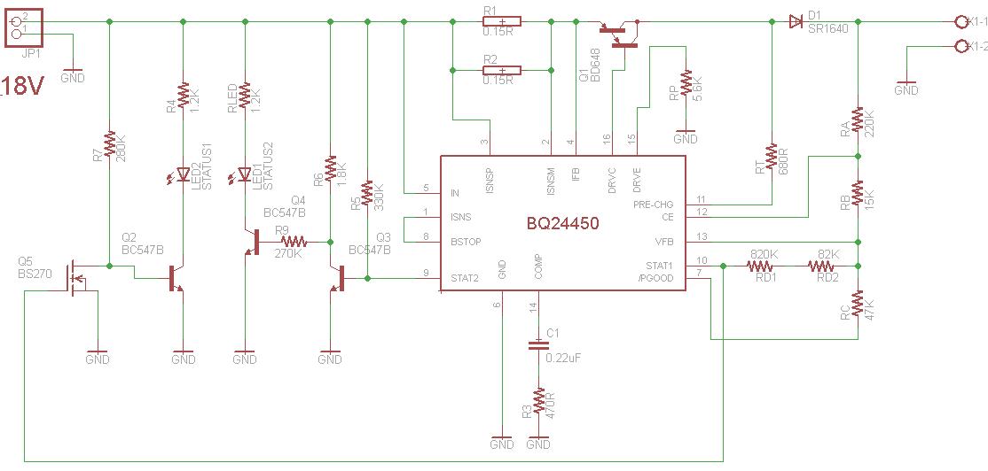
I have two solar panels in parallel conection which produce an output of 18V and 7A together (in full sunshine). I want to charge a car battery with characteristics (12V and 63AH). My charger specifications are these below:
I decided to charge this battery with this 18V output and a Imax current Imax=3.3A. => That means the value of Risns is: Risns=250mV/3.3A=75mOhm.
Vth=10.8V (1.8V/cell) Vth= Vref * (RA+RB+RC//RD) / (RB+RC//RD)
Vfloat=13.8V (2.3V/cell) Vfloat= Vref * (RA+RB+RC) / RC
Vboost=14.4V (2.4V/cell) Vboost= Vref * (RA+RB+RC//RD) / (RC//RD)
As it is obvious i decided to make the Charger with Pre-Charge at page 10 of the datasheet.
My values are : RC=47K , RD=902M (820K +82K) , RA=220K , RB=15K
My first question has to do with the pass transistor. Since my Imax-chg is 3.3A the only topology that meet my requirements is the External Quasi-Darlington. This topology is slightly different from the common PNP darlington topology found in integrated darlington transistors, and it can be implemented only with discrete transistors. For that reason, I decided to use the BD648 PNP darlington transistor with a beta more than 1000 when Ic is 3A. Does the choice of this transistor has any effect on the performance of the circuit? The calculation of Rp is still the same? The VIN(min) value is 18V right?
My second question is for the STATUS1 and STATUS2 pins. I would like to have an indication with two leds about the charging state each time. There is no need to use a microcontroller because there are no other operations to be done. A simple indication with LEDS will be the best. When a status pin is ON I prefer the corespondent LED to operate. According to this requirements do you have any reccomendations in the posted schematic? Are there any other ways reccomended ?
In status1 I use the N mosfet BS270 because the RD resistor is so big that the current is not enough to bias a normal bjt transistor.
Thank you in advance
