This thread has been locked.

If you have a related question, please click the "Ask a related question" button in the top right corner. The newly created question will be automatically linked to this question.

BQ24650: Battery connected to bq24650 in not charging

Part Number: BQ24650
Other Parts Discussed in Thread: CSD18504Q5A, BQ24610, TPS54060, UCC27201

Hello Support team,

I am using BQ24650 IC for MPPT design,  I have designed for 10A  charging current , rigged up  circuit as shown in datasheet but li-ion  battery connected to output is not charging.

Below are the design details:

1.Vin 12V

2.Vmpp 17V

3.Icharge 10A

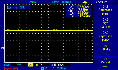
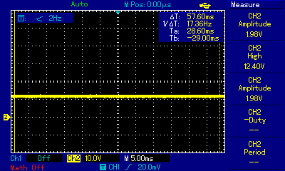
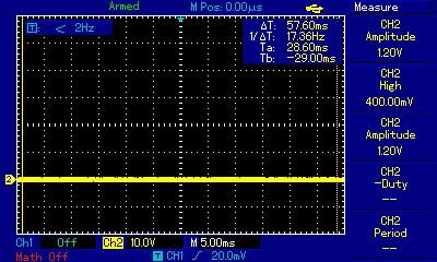
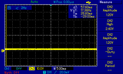
I am getting 1.8V on Vfb pin and  2.4V on Vmppset pin.

Please help me out regarding the issue ASAP.

Regards-

Nagaswaroop

  • Hi Nagaswaroop,

    Welcome to the TI E2E forum!

    Can you send a schematic for this design? This will help on finding the root cause.

    Also, send scope screenshot of VCC, SRN, PH and REGN. What is the DC voltage on VCC, SRN, and REGN?

    I want to remind that 10A charging current can generate heat, and suggest that there is enough copper pour under the IC and a GND plane to dissipate heat.

    Regards,
    Steven

  • Below are the DSO screenshots of Bq24650's VCC, PH, REGN, VFB, Vmppset and SRN pins:

    Figure1: VCC pin voltage of Bq24650

    Figure2: PH pin voltage of Bq24650

    Figure3: REGN pin voltage of Bq24650

    Figure 4: SRN pin voltage of Bq24650

    Figure 5: VFB pin voltage of Bq24650

    Figure 6: Vmppset pin voltage of Bq24650

    Below are the voltage measured by using digital multi-meter on respective pins of Bq24650:

    VCC=24.22V

    PH=11.56V

    SRN=11.56V.

    REGN=0V

    Vmppset=1.985V

    VFB=2.42V

    Attached is the schematic of Bq24650 MPPT design

    MPPT-12V 10A Li-ion revised 1.pdf

    Please help us to resolve this issue ASAP

    Regards-

    Nagaswaroop

  • Nagaswaroop,

    VFB is higher than the regulation point of 2.1V, meaning that your resistor divider for VFB is not properly configured. If VFB is higher than 2.1V, then it thinks that the battery does not need more charging.

    In the schematic I find a few things that need to change:

    1. C10 to 22pF

    2. R1 to 100k and R2 to 500k or similar (need to verify the correct ratio, as VFB needs to be lower than 2.1V to start charging)

    3. I recommend using surface mount FET for less parasitics

    4. Remove C8 and C9. Replace with 4x10uF caps. Place all 4 caps after SRN sense resistor.

    5. Make sure that in the layout SRP and SRN are in Kelvin connection.

    6. Please try to use a single inductor, and its recommended to use 3.3uH.

    7. With a sense resistor of 5mohm, your regulation current will be 8A. A sense resistor of 4mohm is needed for 10A charging current.

    8. Your MPPSET is set to 18V, which for 17V you would need to adjust the resistor divider, to a ratio closer to 13.17.

    8. Use the calculation tool to calculate values if needed.

    Follow the picture I attach here for the power stage, it is the optimized way to layout a buck converter. Reduce loop on input and output currents.

    Let me know if you have any questions on this.

    Regards,

    Steven

  • Hello StevenB,

    Thanks for your valuable inputs, we will make the changes accordingly and let you know the results.

    We used 33µH having 3A saturation current ,since we need saturation current more than 10A for our design, we connected 4nos of 33µH having 3A saturation current. And below are the few  more queries on current design:

    1.Is Vmpp and Vin voltage are same? 

    2.I have designed input voltage regulation for Vmppset=18V , battery voltage regulation for 12.6V,theoritical duty cycle obtained for 
       vin=18V and vout=12.6V is 70%, Iripple is 1.909A , Isat>=10.9545.

    Below are the practical voltages observed when I connect the digital Multi meter -ve probe at Signal GND(battery GND):

    Voltage measured on power supply is 12.50V.

    For Vin 12.16V, voltage obtained on Vmppset pin is  0.814V

    For Vbat 11.29V,  voltage obtained on Vfb pin is 1.87V 

    Voltage on top side MOSFET gate is 11.57V , drain is 12.38V, source is 11.57V

    Voltage on bottom side MOSFET gate is 0V , drain is 11.57V, source is 0V.

    Below are the practical voltages observed when I connect the digital Multi meter -ve probe at BQ24650 IC pad (main GND):

    Voltage measured on power supply is 12.50V.

    For Vin 12.38V, voltage obtained on Vmppset pin is  1.040V

    For Vbat 11.51V,  voltage obtained on Vfb pin is 2.096V 

    Voltage on top side MOSFET gate is 11.57V , drain is 12.38V, source is 11.57V

    Voltage on bottom side MOSFET gate is 0V , drain is 11.57V, source is 0V.

    I have connected two GNDs through 600ohm bead resistor and used SR3100 diode in place of Q1(P-CHANNEL MOSFET).

    By practical  observation we found that voltage on Vfb pin is below 2.1V, even then battery is not drawing current, can we know the reason for this?

    Please help us ASAP.

    Regards:

    Nagaswaroop 

  • Also can we know where we can find calculation tool for Bq24650 design?
  • One more update, voltage on Vref pin is 0.404v even after setting VCC= 22V of Bq24650 and we placed bq24650IC on daughter card and rigged up the circuit in bare PCB.

  • Hello,

    Since we are not getting 3.3V at Vref pin of Bq24650 IC, we replaced IC with new one ,now we are getting 3.3V at Vref pin, but end result remains same i.e battery is not charging. while reading datasheet I found , TC pin connected to NTC should be within the programed voltage limit to enable charging. So I considered VLTF=72.5% VTCO=44.3% and VHTF=46.7% and designed accordingly. The values which I got w.r.t Vref is VLTF=2.3925V and VHTF=1.5411V , the practical voltage which I am getting when NTC connected to TS pin is .77V, which is out of range, so for testing purpose I gave external battery voltage(2.07V) to TS.

    Below are the practical results:
    When battery is not connected or Connected, LODRN giving 6V and I am getting short signal across R2 to R1(i.e load). Status 1 LED turn on ,then external battery voltage(2.07V) start decreasing and status 1 LED turn off after 1.47V.

    Please help to resolve this problem ASAP.

    Regards:
    Nagaswaroop
  • Hi Nagaswaroop,

    You may have to fix the TS resistor values in order to get the correct voltage at TS pin. I think I gave you the link for the calculation tool on my first post. Here it is again www.ti.com/.../sluc175 .

    It also looks like you are confusing the functionality of MPPSET. MPPSET is used to regulate input voltage, because for a solar panel, the maximum power that can be output is a function of voltage. You want to maintain input voltage at the peak power point of the panel.

    If you are using a power supply, the input voltage would have to be at 19V for the charger to operate properly. In the schematic, you designed for 18V MPPSET, which means input voltage would have to be above 18V for it to operate.

    Regards,
    Steven

  • Hello Steven,

    Thanks for your valuable inputs.

    We have few more quires regarding Bq24650:

    1. Recently we have purchased new bq24650ICs from TI, for testing we gave voltage on VCC (up to 4V) when we read the voltage, the same voltage is coming on all the pins of Bq24650
    ex: VFB is input pin but voltage read on this pin 4V for VCC 4V
    we tried with two new IC the result we got as mention above.
    After we compare IC part numbers of old and new IC stock, we found two part numbers are different.

    part numbers as follow:
    Old stock: PAS TI 5AW Z297
    New stock: PAS TI 63w Z38F

    Old stack ICs is working fine.

    Please let me the reason for this.
    NOTE: We tested IC alone.

    2. In schematic mentioned in datasheet we can find two different types of GND. We have connected both the ground using 600ohm ferrite bead resistor.Is this the proper way to connect?

    Please let me know on this ASAP.

    Regards
    Nagaswaroop
  • Nagaswaroop,

    What was the reason to conduct this test? Did you try to supply input voltage with a 19V power supply and see if it worked?

    Both GNDs should be connected with a short, not a ferrite bead. To reduce noise from the power ground to analog ground, you need to connect them at a single point very close to the IC, preferably under it. You also want to connect the thermal pad to a good GND plane with vias to dissipate heat.

    The bq24650 build has not been changed from my understanding. They should be the same silicon, but of course from different lots. What was your setup for this test? Did you try on the board?

    Regards,
    Steven
  • Hello Steven,

    I have tested by giving 19V for VCC, but battery is not charging, that's why I performed IC test. Today I  shorted two GNDs, gave 19V VCC and checked circuit board but now also battery is not charging.

    Is it possible to provide us sample evaluation board for testing?

    Regards-

    Nagaswaroop


  • Nagaswaroop,

    I just noticed in your schematic has Q1 that is not connected to any other signal. Short out Q1 and try again. For the final schematic, you want to change Q1 to a diode. Try to have 19VIN, 11.1VIN, TS at 2V and short Q1. This should enable your charge.

    You can purchase an EVM from our TI website.

    Regards,
    Steven

  • MPPT-12V_10A_LI-ION_V1_1.pdfHello Steven,

    Has I already mentioned in my previous mail I am using SR3100 diode in place of P-channel MOSFET(Q1) at input.

    For your reference I am sending the edited  Schematic which contains the Diode (D1) in place of P-Channel MOSFET (Q1)  

    Attached is the Schematic.

    And can I know what is need of Q3 MOSFET at MPPSET pin which uses CE signal.

    Regards:

    Nagaswaroop

  • Nagaswaroop,

    Yes you did mention it before. The Q3 MOSFET at MPPSET is there to enable or disable charge, you can control this with and MCU or any external signal. This FET should be off so that the charger can start, assuming that input voltage is above MPPSET.

    Regards,

    Steven

  • Hello Steven,

    Thanks for your valuable inputs.

    Currently we are testing the circuit on bare PCB may be due to stability problem battery is not charging. Now we are designing the PCB with the changes you updated us, we will test on new PCB board and let you know the results.

    Regards:
    Nagaswaroop
  • Sounds good. Let me know if you have any questions on the layout.

    Regards,

    Steven

  • Hello Steven,

    Hope you are doing good.

    We have designed the new schematic by referring  Bq24650IC EVM Board schematic. Please  let us know if any changes need to be incorporated .

    Attached is the schematic of new design.

    Regards,

    NagaswaroopBq24650IC_EVM_CKT.pdf   

  • Hi Nagaswaroop,

    Good to hear from you again. I have reviewed the schematic and here are a few things:

    1. Change C5 to 1uF

    2. Calculate TS resistors based on the calculator on the bq24650 page of www.ti.com/.../sluc175

    3. R6 resistor value is too high, please calculate how much charge current you want with the formula ICHG = (40mV/RSNS). If charge current is 8A, then sense resistor has to be 5mohm.

    4. Use CSD18504Q5A for Q1 and Q2, surface mount MOSFETs have better heat dissipation and less parasitics, which mean better efficiency and smaller board area.

    5. Q3 could be changed to a smaller FET as well.

    6. You may want to change R24 to a higher value so that variable MPPSET works.

    7. C15 should be 22pF

    8. Change R00 to a higher value for variable VBAT.

    I emphasize the fact that its better to use surface mount devices for DC/DC converters in general because of better heat dissipation and reduced parasitics, which improves the switching waveforms.

    For the layout, make sure there is enough copper pour for heat dissipation, keep the switching lines away from sensing lines, and pack the power stage as close as possible, with input caps very close to high side fet, sense resistor very close to the inductor and output caps very close to the sense resistor.

    Regards,

    Steven

  • Hello Steven,

     Thanks for your valuable inputs.

    We considered your inputs,do the changes accordingly  and let you know the results.

    Regards,

    Nagaswaroop

  • Hello Steven,

    We have incorporated the changes which you mentioned  in our design and designed the  PCB layout for the same. Attached is the updated schematic and PCB layout design(with gbr and PDF format15a mppt.zip) , please go through and let us know if changes need to be incorporated.

    Please do the needful ASAP.

    Regards,

    Nagaswaroop

  • Nagaswaroop,

    The thermal pad on the FETs have to be connected to drain. Try to route everything related to PH switching node on the same layer (Input cap, high side fet, low side fet, inductor, sense resistor, output cap).

    Connect all the legs of the FETs to the traces as well, use copper pour to connect all these lines together. All the drains together and all the source together. Use wide traces as these are power traces and require the width for power, especially for 8A charging.

    The C19 cap is not needed, if you want to add a cap here, I recommend lowering it to 0.1uF.

    Also, make sure the sense resistor is 5 milli ohm and not 5 ohm.

    Regards,
    Steven

  • Hello Steven,

    Hope your doing good,

    By considering the inputs given by you, we designed the BQ24650EVM board, but now also we are facing problem in charging battery.

    Below are the readings and issues we are facing:

    Voltage readings w.r.t GND:

    VCC=19.7V.

    MPPSET=1.89V.

    VREF=3.35V.

    TERM_EN=3.35V.

    SRN=12.64V.

    SRP=10.32V.

    REGN=6.11V.

    LODRV=2.88V.

    HIDRV=8.62V.

    PH=5.5V to 6.5V (Varying)

    BTST=5.5V to 8.8V (Varying)

    Ibat (while charging)=5.91mA.

    Vbat (while charging)=12.65V.

    Vbat (while not charging)=12.65V.

    Issue:

    From the above voltage reading except  Vbat (while charging) and Vbat (while not charging) it clear that criteria for charging is met but charging current by battery is in order of mile amps only not in amps. For further details I have attached  containing  the DSO images .

    Please help us to resolve this issue ASAP.

    Regards,

    Nagaswaroop

    1.BTST

    2.HIDRV

    3.LODRV

    4.PH

    5.SRP1

    6.SRP2

  • Bq24650EVM Related Videos

  • Nagaswaroop,

    Please check your sense resistor(R6) is 5mOhm or not. and measure the voltage between SRN and SRP(on C14 as well).

    Alen Chen

  • Hello Alen Chen,
    What is recommended voltage between SRN-SRP and C14 for proper charging?

    Regards,
    Nagaswaroop
  • Hi Nagaswaroop,

    The voltage between SRP-SPN would be 40mV during CC mode and VMPPTSTE higher 1.2V.

    Alen Chen
  • Dear Alen Chen,

    Thank you for your valuable inputs.

     I checked the circuit, yes it was the issue with current sense resister, I was connected 5ohm instead of 5miliohm. Now I am testing with 1miliohm current sense resister, battery is charging in Amps now.

    NOTE: Due to  non-availability  of 5miliohm resister I have used 1miliohm  resister for testing purpose only.

    Regards,

    Nagaswaroop 

  • Dear  Alen Chen,

    Please let us the Test cases,effect of PWM frequency,effect of duty-cycle of High side gate driver and low side driver, effect of voltage on Vmpptset and Vfb pins on charging, to ensure the proper operation bq24650IC.

    Please do the needful ASAP.

    Regards,

    Nagaswaroop

  • Dear  Alen chen,

    Also please let us know what is the efficiency we can achieve using Bq24650

    Regards,

    Nagaswaroop

  • Hi Nagaswaroop,

    For same typical waves you can refer page 9 of the datasheet.
    We can achieve 90~95% efficiency using bq24650.
    Alen Chen
  • Dear Alen  Chen,

    Please explain us that how the Bq24650 maintenance out battery voltage and current constant by increasing or decreasing input PV voltage or current I.e if you we increase PV voltage PV current is decreases or if you we decreas PV voltage PV current increases ,which leads to achieve constant system efficiency. Can you please explain how it is happening.

    Please do the needful.

    Regards,

    Nagaswaroop

  • Hi Nagaswaroop,

    BQ24650 just limit the charge voltage, charge current, input voltage. Allow Vbat lower, charge current lower, input voltage higher the setting.
  • Dear Alen Chen,

    Sorry for the mistakes in my last post.

    Please explain us the bq24650IC internal MPPT operation for different battery charging profile and also explain how it is enabling system to achieve constant efficiency irrespective of input(voltage or current) variation.

    Regards,

    Nagaswaroop.

  • Hi Nagaswaroop,

    What does your efficiency mean? Generally, the MPPT voltage is constantly , is not changed with light intensity. So BQ24650 can regulate the Input voltage to achieve MPPT.
    Alen Chen
  • Dear Alen Chen,

    We are testing bq24650 Operation for lifePo4 battery 12.8v(3.2v cell) 15Ah.

    Below is the procedure we followed:

    1.Setted output voltage without connecting battery to 14V, by varying the pot connected between Vfb pin and battery output. Vfb pin voltage read on multimeter was 2.09v.

    2.After connecting battery for charging,battery output voltage read on multimeter was 13.34V and voltage on Vfb pin was 1.98V.

    LifePo4 battery before connecting for charging was 13.30V.

    From datasheet for fast charging voltage on Vfb pin should be between 1.55V to 2.1V. In our case it was 1.98V I.e its within the fast charging voltage range only even then battery was not charging.

    We tried the same procedure for li-ion 11.1V battery(3.7V cell ), setting output voltage without battery connected, to 12.8V (Vfb pin was 2.09V) .

    After connecting battery output was 11.5v(Vfb pin was 2.089V)it was working fine, but same procedure is not working for lifePo4 battery, please let us know if any changes need to done in circuit.

    Please do the needful.

    Regards,

    Nagaswaroop.

  • Hi Nagaswaroop,

    Please try to discharge you Lifepo4 battery to 12V then try again. If still won't works, please measure all of Pins' voltage.

    Alen Chen

  • Hi Alen,

    We are checking the charging profile with Lifepo4 battery. we made changes as per the EVM  schematic for lifepo4 in voltage divider (R13,R15,R22) w.r.t calculations in the attachment.

    Could you please help us in calculating right resistors values. From  Application note we calculated the charging voltage for two cases as mentioned below.ie

    1) When R22||R15 (Q3 On), the charging voltage range is from 14.26V to 14.61V

    2) when R22 is not in parallel with R15 (Q3 Off), the charging voltage range is from 12.54V to 12.85V

    When  we connect battery voltage of range from 12.85V to14.26V battery will not charge .

    We want BQ24650 to charge the battery from 12.6V to 14.6V window,Please let us know the design changes need to be incorporated.

    Attached is the voltage divider calculations for Charge and recharge voltages as per application report of bq24650 to Charge LiFePO4 Battery   

     slua565.pdf

    Please do the needful ASAP.

    Regards,

    Nagaswaroop

  • Dear Alen Chen,

    We also tried for,

    Vrefrecharge=8.2v (2.05v*4cell)

    Vrefcharge=8.4v (2.1v*4cell)

    But result remains same.

    Regards,

    NAGASWAROOP

  • Hi Nagaswaroop,


    Why do you want to this function? 'When we connect battery voltage of range from 12.85V to14.26V battery will not charge' .
    or you just want to set charge voltage to 14.26V and recharge voltage to 12.85V.
    Can you share the datasheet of your battery?

    Alen Chen
  • Hi Alen Chen,

    Attached is the datasheet of 12.8V 15Ah lifePo4  battery. Guide us to design the circuit for the same.

    Below is the detailed explanation of the issue:

    From application report Vrecharge measured at Vfb pin is regulated to 2.05V and Vcharge measured at Vfb pin  is regulated to 2.1V, we understood the below mentioned points from application note.

    1) If the battery voltage on Vfb pin drops below 2.05V (recharge threshold) the battery will not charge.

    2)As soon as the battery voltage on Vfb pin  becomes  more than 2.05V battery will start charging because its above recharge threshold and stops charging if it exceeds 2.1V.

    In case if there are any other factors need to be considered other than the above mentioned, please update us.

    In our case as soon as we connect  the battery for charging, the voltage on Vfb pin  is drops below 2.05V and  battery is not charging (Refer figure1 and 2). Battery voltage before connecting for charging was 13.30V(when not charging).

    But when we connect the battery of 12.7V (when not charging) for charging , the voltage on Vfb is above 2.05V   and battery will keep on charging (Refer  figure ) till 12.85V and stops.

    Now we need to design the circuit for recharge threshold  of 11.2V and charge threshold  of 14.6V, that means when we connect battery voltage between 11.2V to 14.6V, the battery should start charging constantly till 14.6V.

    Above voltage readings are w.r.t the calculation attached.

    Fi

    Figure 1:When the voltage on Vfb pin drops below 2.05V and  battery is not charging.

    Figure 2:Scaled up version of figure 1 .

    Figure 3:When the voltage on Vfb is above 2.05V   and battery draws continuous charge

    LiFePo4 Module_12.8V-15Ah (6).pdf 

    Note :In figure 1, 2 and 3 Scope images the channel 1 shows HIDRV pulses and  channel 2 shows LODRIV Pulses.

    Kindly do the needful. Awaiting for your valuable response.

    Regards,

    Nagaswaroop

  • Dear Alen Chan,

    Kindly assist on the  mention issue  ASAP , we are awaiting for your valuable response .

    Please do the needful.


    Regards,

    Nagaswaroop

  • Hi Nagaswaroop,

    Just a little discrepancy,

    1)will start charge , If the battery voltage on Vfb pin drops below 2.05V (recharge threshold) the battery will start charge.

    2)As soon as the battery voltage on Vfb pin becomes more than 2.05V battery will start charging because its above recharge threshold and stops charging if it exceeds 2.1V. No, if a not full battery(VFB lower than 2.1 ) connect to charge, BQ24650 will start charge,untill ICHG current lower than termination current and VFB =2.1V. Then if the battery discharge(by system load internal discharg) to 2.05V, BQ24650 will start charge again.

    Alen Chen
  • Dear Alen Chen,

    Please guide us to redesign the circuit to recharge voltage from 11V and stop charge voltage at 14.4v.

    Please do the needful ASAP.

    Regards,
    Nagaswaroop
  • Hi Nagaswaroop,

    Do you care about the recharge threshold? if not please directly set the charge voltage to 14.4V. it is fine.

    Alen Chen
  • Dear Alen,

    We are developing 12/24V MPPT charger  using Bq24650, for 24V PV system Voc is 40V but  Bq24650 Vcc pin maximum voltage tolerance is 33V and pins like STAT1, STAT2, SRP, SRN and PH are also have maximum voltage tolerance less than 36V, what are changes need to incorporated in our design for 24V system.

    Regards,

    Nagaswaroop,

    R & D Engineer

    Renewable Energy Applications & Products – ReAP

  • Hi Nagaswaroop,

    Thanks for using TI E2E. About your design, could you please provide more information including battery, application...etc? So that we can discuss more detail on it. Thank you so much!

    Best regards,
    Ann Lien
  • Dear Ann Lien,

    The we are developing the 12V/24V  15A MPPT LifePo4 battery charger. Currently we are evaluating the 12V system.     

    Our end product system specification as follows:

    Battery Type used: 12.8V 15Ah LIfePo4.

    Auto Sensing:12V/24V battery and PV.

    Help needed from IT support team  on 12V / 24V 15A MPPT charger design:

    1.What are changes need to be incorporated  in our current design.

    2.What are the protection need to  be incorporated  in our current design.

    Attached is the schematic of our current design.

    Note:

    In schematic below are components which are not installed:

    R4,R16,C19,C9,R8.


    In schematic below are the changes did after PCB design:

    1.JP8 and JP5 are open and are directly connected to Vin.

    2.Replaced 5E with 5mE(0.01E || 0.01E).

     bq24650_ckt_v1_0 (Restored).pdf

    Regards,

    Nagaswaroop


  • Dear Ann Lien,

    Kindly reply, we are awaiting for your valuable response.

    Regards,

    Nagaswaroop