This thread has been locked.

If you have a related question, please click the "Ask a related question" button in the top right corner. The newly created question will be automatically linked to this question.

BQ24616: Who to manage reverse current from system side

Expert 3795 points
Part Number: BQ24616

Dear e2e Community,

My customer has got a specific case to solve, when:

- our charger has no AC adapter connected

- Battery pack is not connected

- the customer system generates a reverse current, coming from electric motors which are driven manually, unexpectedly.

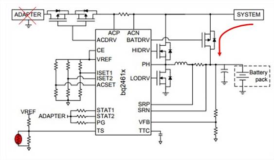
In this case current flow is interrupted.

Have you ever faced this issue in previous design ?

Do we have a tip to drive this current somewhere?

Regards,

  • You can add a schottky diode between system and battery to block system current flow to the battery.

  • Hi Jing,

    In this specific case, the battery pack is disconnected.
    So there is no need to protect it.

    The question is more on: how and where to drive this reverse current, to dissipate it.

    Regards,
  • Hi Prodigy / Jin

    I'am the customer.
    Battery "not connected" means battery power outputs are disabled (due to deepsleep mode, Protection mode, etc)
    In our previous design battery wakes-up and absorbs current regeneration if needed but with BatFet off this function is not ensured anymore.
    As Prodigy said,
    A reverse diode on Power path does not prevent voltage from rising.
    What could be your advice ? Do you know an ingenious way to perfrom this function ?

    Rugards,
  • You will probably want to add an external circuit like below to detect system over-voltage condition. Once the system voltage rises higher than the zener's turn on voltage such that the PFET is turned on to drain the current from VSYS to ground.

  • Dear Jing,

    What I undersand is that your schematics is always ON. Zenner diode will only limits its voltage drop but do not prevent Pfet activation in normal range of Vsyst..

    Please find anoher proposal:

    NMos + Power resistor R3 to dissipate re-injection current.

    When voltage goes above D2 Zener Voltage, Current through R2 rises up to Vgate thershold min. D1 is to protect Vgate max if Vsyst is too hight.

    What's your opinion on it ?

  • The circuit in my previous post, the zener turn on voltage should be higher than the input voltage to prevent the PFET turning on. However, your circuit should work as well.