This thread has been locked.

If you have a related question, please click the "Ask a related question" button in the top right corner. The newly created question will be automatically linked to this question.

BQ24192: Charger chip damage

Part Number: BQ24192

Hi, 

I am using bq24192 charger chip on my custom board. I have tested internal switcher output by applying 5V at VBUS pin and it is working fine. I am getting 3.7V.

Then I have removed 5V from VBUS pin & connected DC 3.3V to BAT pin to check the minimum system voltage (3.5V) at SYS pin, After that, I found BAT pin get shorted with the Ground connection. The 3.3V on STAT, INT & CE pin pull-up resistors were Off at that time of damage.

What could be the cause of this issue?

Attached my schematic here for review & suggestions. 

Appreciate the early response.

bq24192 Charger SCH.pdf

Regards,

Ritesh.

  • Hi Ritesh,

    I looked over your schematic and don't see any issue which would cause this problem to arise.

    May I have some more information to help solve your problem:

    1. When applying 5V VBUS to the device, where do you measure 3.7V? SYS pin, or VBAT?
    2. When you say that the pull-up resistors were OFF, do you mean they were pulling down, or that the pins were left floating?
    3. When applying 5V VBUS, can you measure the voltage at SYS with CE pulled up?
    4. How do you measure that BAT is shorted with ground?

    Thanks,

    Parker

  • Hi  Parker,

    Thank you for the quick response.

    See my response below:

    1. When applying 5V VBUS to the device, where do you measure 3.7V? SYS pin, or VBAT? [Ritesh] on SYS pin

    2. When you say that the pull-up resistors were OFF, do you mean they were pulling down, or that the pins were left floating? [Ritesh] No they were not pulling down. The 3.3V was not there, so they were floating.

    3. When applying 5V VBUS, can you measure the voltage at SYS with CE pulled up? [Ritesh] I have measured 3.7V with CE floating.

    4. How do you measure that BAT is shorted with ground? [Ritesh] I have measured using Multimeter setting in Ohm meter.

    Thanks,

    Ritesh.

  • Hi Ritesh,

    The charger operation is based off of a given state of the digital inputs. With the digital inputs floating, the behavior of the part will be undefined.

    Can you pull up the CE pin of the device, and set the other inputs as desired for your application, and take the SYS voltage, BAT voltage, and get the value of all of the registers while in this condition?

    When you measure that the BAT pin is shorted to ground is the device powered?

    Thanks,

    Parker
  • Thank you for your time again.
    But the pullup resistor connected in my design will be getting power after charger chip SYS power. Sys pin is connected to PMIC in my system & that is generating 3.3V.
    Without connecting 3.3V or battery voltage to BAT pin bq24192 works fine as a buck converter.

    Also, the device was not powered during impedance measurement.

    Thanks,
    Ritesh.
  • Hi Parker,

    We have applied DC 3.3V to BAT pin from another power source, Now I found that it only supports 300mA, whereas our board is taking more than 1.5A @ 3.3V.

    Do you think this can be the cause of this chip damage?

    Thanks,

    Ritesh.

  • Hi Ritesh,

    A few questions for you:

    1. Is the 300mA into the charger or out of the charger?
    2. Where are you measuring the load of the board? Is this being measured out of the SYS pin?
    3. Are you connecting a VBUS to the device as well? If so, what voltage and current do you set/measure on this input?

    Additionally, to clarify on your previous post: pulling up the inputs to the device directly to the SYS pin (or the REGN pin) will work to set the inputs. However, leaving these pins floating will not work.

    Regards,

    Parker
  • Hi Parker,

    See my response below.

    1. Is the 300mA into the charger or out of the charger?

    [Ritesh] into the charger @BAT pin

    2. Where are you measuring the load of the board? Is this being measured out of the SYS pin?[Ritesh] yes, load is connected to sys pin after capacitor filters.

    3. Are you connecting a VBUS to the device as well? If so, what voltage and current do you set/measure on this input?[Ritesh] I am not connecting VBUS to the device while connecting the battery to BAT pin.

    I have replaced cahrger chip now on my board & connected battery to BAT pin. Successfully got voltage on SYS pin now. But not able to run the system.

    Is there any current limitation in internal Q4 Mosfet of bq24192? Because my system is taking 1.5A & it is not working with battery (2AH charged) connected to the BAT pin.

    Additionally, to clarify on your previous post: pulling up the inputs to the device directly to the SYS pin (or the REGN pin) will work to set the inputs. However, leaving these pins floating will not work.[Ritesh]but i have connected those status & control signals to my procrssor, 3.3V ttl level. The sys & REGN can go higher than that, correct?? Which may damage the processor IO.

    Thank you.

    Regards,

    Ritesh

  • Ritesh,

    What current do you measure at the SYS output? How much current are you expecting / what type of load do you have?

    Can you measure the voltage drop over the Q4 device when the BAT voltage is sourced and the SYS load is applied? You can use the measurement of current at BAT to calculate the RDS_on of the Q4 FET to compare against the datasheet value.

    The Q4 FET should not limit the current until it reaches BAT OCP, which is around 7A. Once the OCP trips, the FET will latch off.

    While in this state, can you provide the values in the registers read over I2C?

    Additionally, on the schematic posted earlier, the TS resistor network is marked as DNP. Are these resistors populated?

    Regards,

    Parker
  • Hi Parker,

    See my responses, 

    What current do you measure at the SYS output? How much current are you expecting / what type of load do you have? [Ritesh] There is no current at sys out. I am expecting 1.5A current as my system takes 1.5A current while running.

    Can you measure the voltage drop over the Q4 device when the BAT voltage is sourced and the SYS load is applied? You can use the measurement of current at BAT to calculate the RDS_on of the Q4 FET to compare against the datasheet value. [Ritesh] There is no Voltage drop across Q4 device, I am connecting 3.89V on BAT pin & getting 3.89V on SUS pin. Current at BAT pin in this state is 40mA.

    While in this state, can you provide the values in the registers read over I2C? [Ritesh] I am not able to read register value in this state as my system is not running with battery connected.

    Additionally, on the schematic posted earlier, the TS resistor network is marked as DNP. Are these resistors populated? [Ritesh] No, These resistors are DNP. I am connecting NTC thermistor on fuel gauge.

  • Ritesh,

    Do you have an EVM available? If so, can you power the system off of the EVM SYS output to rule out any issues with the custom board?

    Can you measure the voltage output of your LDO?

    Can you place a known power resistor producing more than 500mA current from SYS to ground and measure the current over this resistor? I want to verify that there are no issues with the load and that the BATFET can turn on.

    Regards,

    Parker
  • Hi Parker,

    We don't have EVM available. 

    I found STAT pin blinking at 1Hz, which means there is some fault condition arise.

    This STAT pin blinking in both cases, With or Without connecting battery to the BAT pin.

    I think we have to debug that fault condition before moving for the battery charging.

    Looking at the Schematic, I don't find any issue that crease the fault condition. Can you recheck schematic?

    Regards,

    Ritesh.

  • Ritesh,

    If the resistors on TS pin are DNP, and this pin is floating, then this is the source of the fault.
    The best way to know for sure is to read the fault/status registers from the device. Do you have a I2C communication device that you can use to read the register values? Then we can deal with the faults that we know are present in the system.

    Regards,

    Parker
  • Hi Parker,

    I have measured the signal on STAT pin and there was 1Hz clock indicating charger fault condition.

    Then I have connected resistors on TS pins and programmed the temperature window & removed fault condition. Now my system is working fine on SYS power rail for this board.

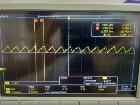
    But I am getting saw-tooth kind of waveform on BAT pin. See attached image for BAT pin waveform. I have not connected battery till with Charger chip and CE pin is high (pulled high by 3.3V rail). Not able to understand why there is voltage available on BAT pin,

    At the same time, today on my other two boards I found SYS & BAT & GND pin shorted with each other(showing 1ohm impedance between SYS & BAT pin and 8ohm impedance between BAT/SYS & GND pin). These two boards Power management path (Vsys) were working fine till today. I have not connected battery to these boards.

    Any idea about this unpredictable behavior of charger chip.

    Appreciate your support here.

    Regards,

    Ritesh.

  • Hi Ritesh,

    Need more information and details for your system. Let's take this offline.

    Parker