This thread has been locked.

If you have a related question, please click the "Ask a related question" button in the top right corner. The newly created question will be automatically linked to this question.

BQ28Z610: RSoC and Remaining Capacity Error

Part Number: BQ28Z610
Other Parts Discussed in Thread: BQSTUDIO

Hello,

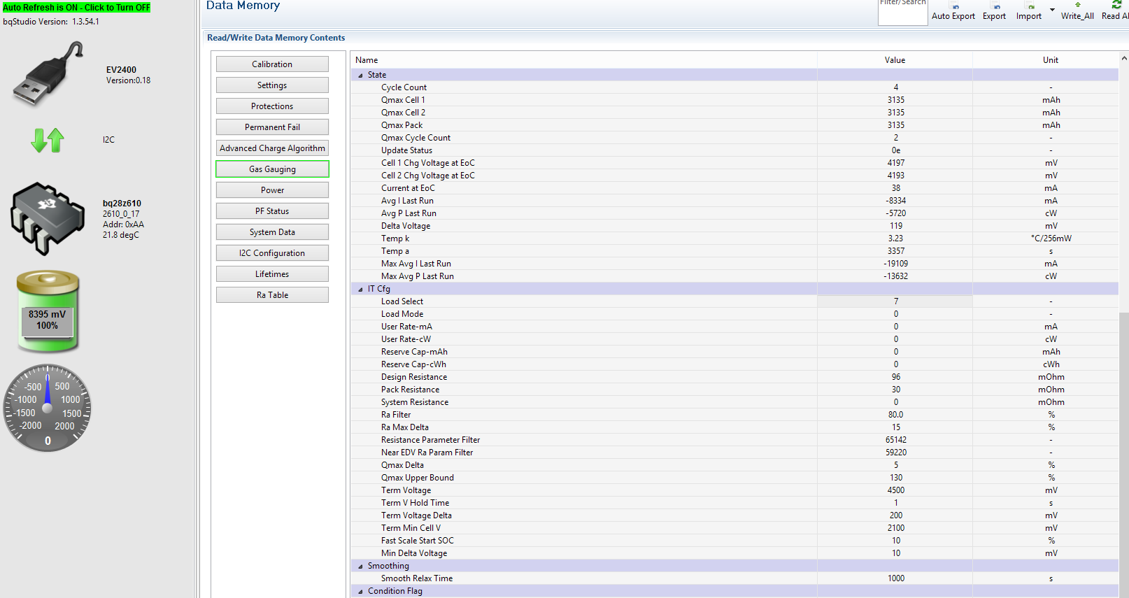
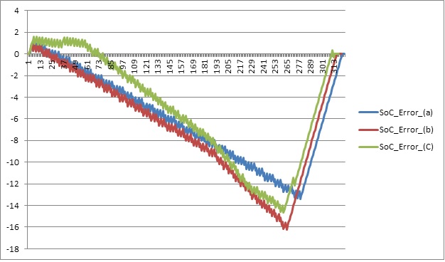
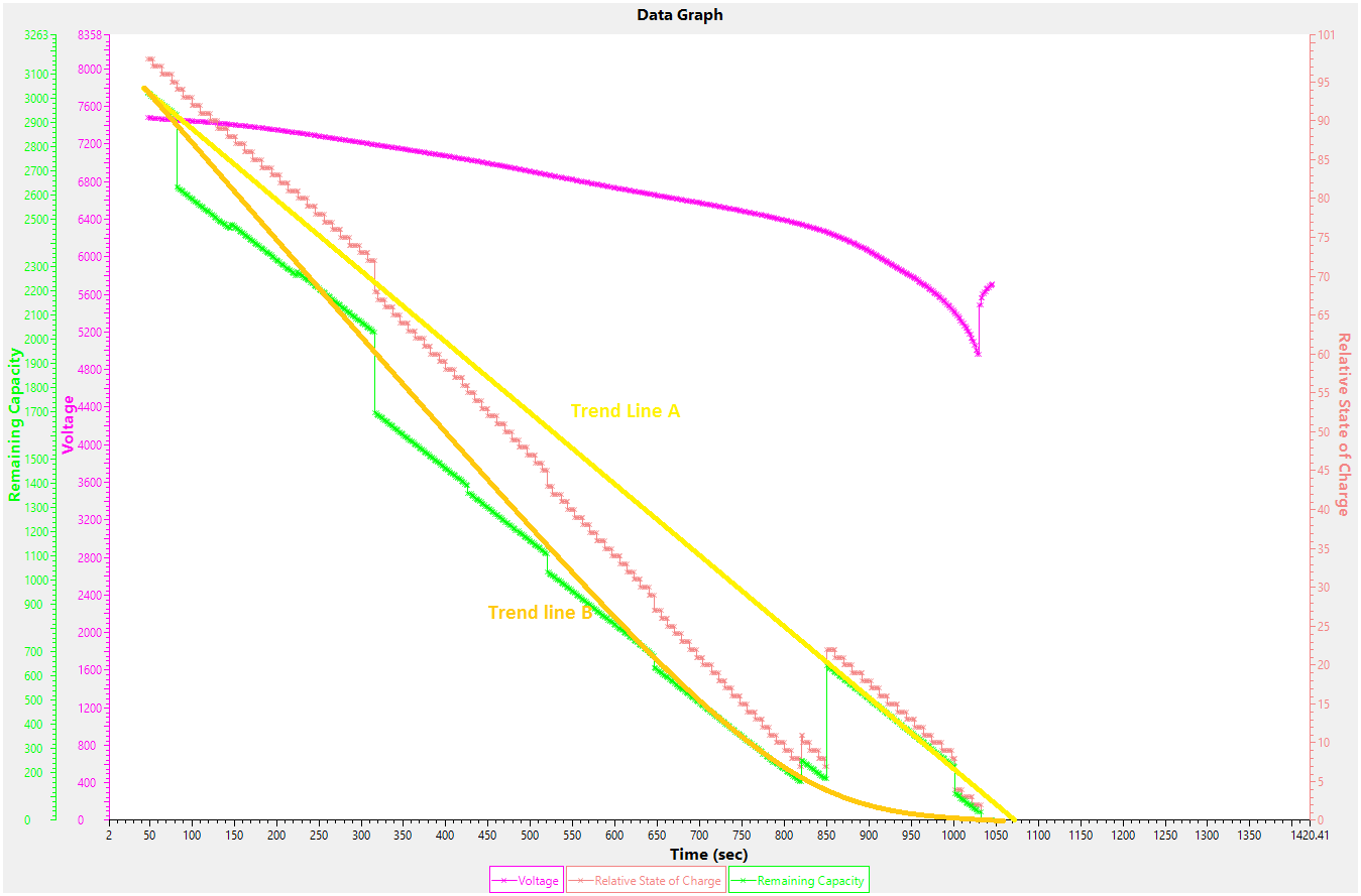
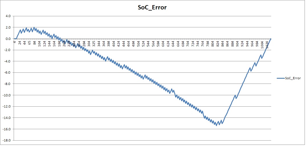
I am testing a 2-cell battery with bq28z610 and Sony US18650VTC6. Chemistry update and learning cycle were done. However, the application current is much higher than the current used during the learning cycle (10A vs 0.6A) and I am seeing a huge error in RSoC, something like 15-20%. I have done controlled discharge with different currents and the maximum error is acceptable at 1A - about 2.5%, at 5A it becomes 8% and at 10A it is 16%. I have noticed a trend that the gradient of the Remaining Capacity curve is always 'pessimistic', i.e. it reduces faster than it should and at the very end (below 10% RSoC) it starts compensating but by that time the huge error has already developed.

Attached are the graphs of the RSoC error and the GG Remaining Capacity vs the calculated one. (Calculations as per the TI E2E™ Community guide How accurate is your battery fuel gauge?)


I am stuck with this problem and I am incline to think that the issue is somehow higher impedance included in the GG algorithm, but have no idea where to look and correct it

Regards,

Peter M

  • I think that has to do with your load select. Given that the current is much higher, more than 15x the rated learning current, you need to use load select of 1, 2 or 3 so that the impedance track calculations use your current rate of dsg.

  • Hi Batt,

    Thanks for your suggestion. However, I have already tried this and it did not work. The default Load Select is 7, which is the Max AVG last Run, and indeed when I look at the recorded value for the last run it is 10A or very close to it, so the IT should use that value anyway. I have tried with Load Select 1 and 2 and wanted to try 6, but for some reason I could not enter a value different than 0 in the field User Rate (mA).

    My next step was to change the Design Resistance because it stays at 96mohm, which is the default value, but surprisingly it only affected the Full charge capacity - after the learning cycle I had Qmax at 3100mAh and the values of the FCC after every discharge were between 2950 and 3050mAh, which is expected with those cells. After reducing manually the Design resistance from 96 to 60mohm, the FCC dropped to between 2200 and 2300mAh, which does not make sense since in the Technical Reference it states that the Design resistance is the average cell resistance at grid point and those are only updated during discharging.

    I have also tried a new learning cycle with passing 5A during discharge, but it did not work at all. I would appreciate any other suggestions.

    Best regards,

    Peter M  

  • What version of the 28z610 fw are you using?
  • The gas gauge is rev 2610_0_17 according to the Battery Management Studio

  • Hi Peter,
    Did you already attach your .gg.csv file so that we can see your configuration?
    If not, can you please share you .gg.csv file (ideally before and after your test) as well as the log file showing all gauge registers during the test?
    Is this using a TI EVM or a custom PCB?
    In either case, is the thermistor physically attached to the cells and accurately measuring the cell temperature?
  • Hi dMax,

    Please, see attached the gg file of the golden sample. I have not got one after the first tests and have done quite a few changes since, so it might be irrelevant.

    Attached are also two 10A log files, one 1A and one 5A from my tests.

    Kind regards,

    Peter MDischarge10A.logDischarge10A_2.logDischarge1A.logDischarge5A.log

  • Sorry, forgot the gg.csv file. I am using both custom made PCB and Eval Board with exactly the same results.

    FW_20180408.gg.zip

  • Thanks, do they both have the same config?
  • Hi Batt,

    Yes, both Eval Board and test Battery 2 have the same configuration, set up using the same golden sample srec file (attached). Battery 1 has been modified to have Load Mode/ Load select 1/1.

    EV_2141_FW_20180408.zip

    Regards,

    Peter M

  • Thanks, I'll have it checked out and reply back to you
  • Hi Batt,

    Do you have any comments on this issue. Does anyone at TI have any comments? It is frustrating that there is nobody knowledgeable to what this error is caused by. Is it the Impedance Tracking algorithm itself or is the Sony US18650VTC6 Chem_ID in the database wrong? 

    I am really separate and while I was waiting for a response, I have purchased an Eval Kit from one of the competitors, and the accuracy at exactly the same conditions is always below 3%. It's a shame the bq28z610 is such a rounded solution - gas gauge plus a front end with primary protection, but let down by poor accuracy. Even at the cost of redesigning the BMS, I am now considering scrapping the current solution if there is no improvement in the accuracy as this is paramount for our customer.

    Kind regards,

    Peter M 

  • Peter,

    Sorry, I understand your frustration but we needed to confirm if this was an issue with our chem ID. Sorry for not posting here or keeping you updated but we have information. The chem ID for the cell is correct. You are discharging all the way to 2V per cell. Please retest with your terminate voltage set to 4000mV. That should hopefully fix your problem.

    I apologize, we are not the best at keeping you updated but you can always be sure that we will be attentive to helping you when you post in our forums.
  • Hi Batt,

    If only it was so easy. Changing the Termination voltage was the first thing to try, and it did help somehow slightly - instead of dropping to zero the RM curve started folding and converges to zero at termination, but this only changes the error from 20% to about 16%.

    The same issue has been looked at by a TI FAE in the South East of China (Guangzhou) where the battery is being manufactured, and their suggestions were:

    - create a new golden image, using the following changes, and run two complete cycles, however there was no improvement after those two complete cycles, see attached the S0C error of each of the three cycles (I did three)


    Initial Value

    Change

    IT Gauging Configuration

    15ce

    1206

    Load Select

    7

    1

    Outside Temp Time

    7200

    1

    Temp Condition

    1000

    0

    Temp k

    1.26

    6.75

    Temp a

    4250

    5166

    It seems to me there is a fundamental issue with the impedance tracking in this case (golden image generated at low current and battery used with much higher one or the Chem_ID is wrong, it dos bear the name US18650TVC6, not VTC6, although such cell does not exists.

    Regards,

    Peter M

  •  And the graph with the SoC error, a - first cycle, b - second etc.

  • Hi Peter,

    I thought that the battery number was a typo, so I discounted that as a probable cause. You have used smoothing in your settings to prevent jumps in your RSOC. Can you please disable that and test it? I analyzed your logs before sending them to our chemistry people. This chem ID does terminate at about 2400mV. At this point, the OCV curve slope is almost 150 degrees. Your loss of capacity between 2500mV and 2000mV is about 44mAh, that's less than 1.5%. What I'm seeing is there is a very late change in Ra scaling which I'm suspecting is causing a large drift that is uncompensated due to smoothing. Disabling it will help us see if we are getting a wrong RM estimation at the first grid point or if this is an artifact of the chemistry. If it's the latter, we may need to do a chem ID matching again and see if that helps.

    Can you please do that and send the logs over?
  • Hi Batt,

    I will test the battery with disabled smoothing tomorrow and post the results here.

    There was one more thing I wanted to clarify - in older IT gas gauges the first check of the RM and FCC was done after 500 seconds to prevent error from transient. However with discharge rates greater than 3C this is happening after the first and probably also the second grid point. Is it possible that this could be the reason for the big error. What is this timing for bq28z610?

    Regards,

    Peter M

  • Thank you, Peter. Also, we have released v20 with some bug fixes to IT. Can you please upgrade to that as well? The OCV wait is still the same. Your application is rather unusual in that it has a very sustained high rate of dsg. As you mention, you do run through grid points rather quickly. However, IT simulations for remcap start with your load select the moment dsg starts. So, in effect if there was an error, it should be right from the start of dsg. It may probably have been masked by smoothing. That is what we're waiting to verify.
  • Hi Batt,

    The test run without smoothing just proves that there is an error of about 20% and the gas gauge 'brain' only realises that error exists at the very last minute - when only 5-6% od the SoC is remaining. Attached are the log file and screenshot of the bqStudio graph.

    I have the following questions:

     1. If the Chem_ID grid points do not take into account the increased temperature (up to 50degC rise) and its effect on the cell internal resistance, would that be enough to cause this error?

     2. Attached is also a screenshot where I have added some trend lines, would that be any help of understanding the issue:

      - trend line A would be the ideal response of the gas gauge, why isn't it followed for the rest of the discharge, but only for the first couple of minutes, and only after reaching 5-6% SoC it gets back to it

     - trend line B is the response I have been seeing so far with the smoothing.

    Kind regards,

    Peter M

    Bat2_10A_no_smoothing.zip   

  • Peter,

    Thank you for the details. It looks to me that the initial estimation at the grid point tends to severely underestimate capacity. Yes, self heating of the cell can increase capacity but that is minimal. Maybe you may find 1% or so change. Not beyond that. After internal discussions, we have the opinion that your chem ID is not matched well. We are consistently seeing an underestimation which should correct itself after load compensation. This load compensation is based on avg I last run. Again this value in your srec that you sent me was set to -600mA. That needs to be set to -10000mA. It should automatically update at the end of dsg. So, I have no idea why it remains the same old value you used in your golden gg.

    My advice to you is,

    1. After your LC, please set your avg I last run to -10000mA, reset your gauge and then wait for it to take OCV and start a cycle again.
    2. Do another chem ID match. It is possible that your cell might not be the chem ID 2141 that you are using.
  • Hi Batt,

    Perhaps you are looking into an early (just after the LC) srec file. If I check now, the AVG I last run is indeed -10000mA. As per the Chem_ID, I am positive the cells we are using are genuine Sony US18650VTC6. Is it possible that the TI database file with Chem ID 2141 was not created with those cells and it is labelled by mistake VTC6?

    I am doing now another learning cycle with the v20 FW. Any suggestions for the DSG current? Stick to 600mA or go for a higher current?

    Regards,

    Peter M
  • Hi Peter,

    That is perhaps the last option that we need to look at. I looked at the chem ID. To me it looks good. Your flat region is higher at 4V which is seen in cells rated for high dsg. That along with the fact that the OCV curve goes near vertical at terminate indicates a good match. However it is possible that this could have been wrong. I can't totally discount that. It is with that view that I'm asking you to re-run your chem ID match. In any case, did you match the cells before your LC or did you just pick it from our list?

    For the LC, go ahead with a C/2 rate. That would be between 1500-1600mA. At the end of the LC (after 2 chg-rel-dis-rel) cycles set your avg I last run to -10000mA prior to your actual test. Let's see what this gets.