


I have a questions about the BQ20Z655-R1 chips that we currently use in some of our products. While programming some of these chips using a MIIC 203 iport/AFM I2C host adapter some of the calibration data is getting corrupt. I can use the bq evaluation software to see the areas of calibration that are incorrect. We would like to try and make our code more robust in order to handle these errors. The problem I’m having is converting the byte data into something I can’t use to see if a value like the CC Gain is within the min and max for this chip.
For example, using the MIIC 203 I can read back ~15~81~6E~90~04~94~07~B7~31~5F~93~05~08~56~22~F8~C0~FF~63~00~FB~00
From a product that is calibrating correctly. The first 4 bytes (~81~6E~90~04) after ~15 would be the CC Gain. How do I convert this into a value that I can compare to the CC Gain min and max for the BQ20Z655-R1? The same explanation for how to convert cc Delta, ref Voltage, AFE Pack Gain, CC offset and Board offset would be great.
I have looked online and I’m unable to find this information.
An example of the correct data I’m seeing in the bq evaluation software for calibration:
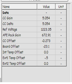
How do I convert from the DF data to the data I’m seeing in the BQ evaluation software?

