


Other Parts Discussed in Thread: BQ78350, BQ76200, BQ76930
Recently, I did a PCB design consisting of the bq78350, bq76930, and the bq76200. The header that is in the battery is shown in Figure 1 and the header it connects to in the system is shown in Figure 2.
Pin Explanations:
Pin 8 and 7: The SMBUS (SMBD and SMBC): These pins go from the bq78350 to a microprocessor in the system.
Pin 6: BATTV: It is a current limited pin on the Battery side for us to check the direct battery voltage. It is unconnected on the system side.
Pin 5: The System present pin which is connected to the bq78350 and is used to turn on the battery only when the battery is in the system by pulling to low. It is pulled to Pack- on the system side.
Pin 4 and 3: PACK - : This is the high current return path that, on the battery side, is connected to BATT - through the current sense resistors and is the High Power Return path for the system.
Pin 2 and 1: PACK + : This is the high current supply that, on the battery side, is connected to BATT + through the high-side FETs and it supplies power to the system.
The Questions:
1) Once mated, the only return path for the SMBUS is PACK - . Are there any issues that can come up by doing this? Is there anyway that noise on this line can cause system failure?
2) Once mated, the System Present pin is connected to PACK - . Are there any issues that can arise from this? Can this cause system failure?
I am asking this question because we have had a couple system failures where it seems as if the system just stopped getting power. We want to investigate the battery system as a potential issue.
I have recently changed the pin out of the connectors where pin 6, instead of being the battery test voltage is now a digital ground return that connects to ground to which the bq78350 is connected and the ground to which the microprocessor is connected on the system side. See the last picture: figure 3
Thanks,
JP

Figure 1: Battery Side Connector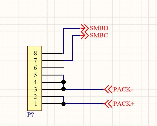
Figure 2: System Side connector

Figure 3: New Battery Side Connector

