This thread has been locked.

If you have a related question, please click the "Ask a related question" button in the top right corner. The newly created question will be automatically linked to this question.

UCD7242: unusual SW waveform

Part Number: UCD7242
Other Parts Discussed in Thread: TMS320C6678, , UCD9244

I use UCD9244 + UCD7242 to power TMS320C6678 CVDD.

There are two board, one is work fine.

Another one will encounter FLT condition when the current increase to about 4A.

The GUI only report FLT condition, no other error occurs. 

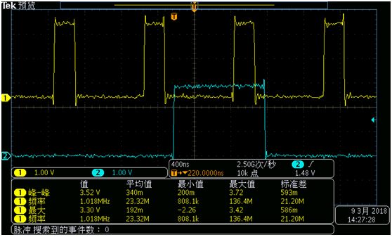
When I probe the SW signal, I find that the SW signal of the one board is always like this.

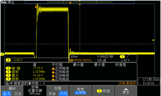
When the current is increasing, the SW signal of the another board become like this.

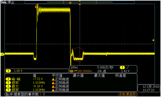
I point out the unusual waveform with red cycle.

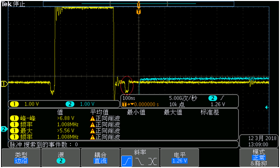
When the width of the unusual waveform increase, the FLT condition occurs.

channel 1 is SW and channel 2 is FLT.


Why?

Thanks

  • Xiao,
    Please let me review this question with some experts and get back to you as soon as possible.

    Hopefully I will have an update for you within 24 hours.
  • Thank you very much.

  • I'm still in discussions with some of our experts on this but we had a few more questions and/or suggestions:

    1) Are these identical boards with exact same Imon parameters?
    2) What is the value of the resistor connected to this(ese) pin(s)?
    3) What’s the value of Vin, Vout, Fsw, Lout and maximum Iload?
    4) Can you club the waveform of the external PWM with SW?
    5) Are both SW-A and SW-B witnessing the same fault problem ?
    6) FLT can be asserted for overcurrent and over temperature. Are both the boards run under same thermal operation ?

    One way to isolate the problem would be to de-solder the DSP (TMS320C6678) and connecting a regular programmable load to the output of the buck converter and see if the problem continues. If it stops giving FLT then the problem might be with the DSP instead.

    Similarly, if a function generator is used to feed PWM signals to the UCD7242 instead of UCD9244 and this results in removing FLT, the problem might be with the Digital PWM Controller instead.
  • Thanks, Brett Barr.

    Here are some details.

    Our design base on TMS320C6678 EVM, we only add more capacitors to CVDD rail.

    There are two TMS320C6678 on one board, we use UCD7242 to power each TMS320C6678 CVDD.

    For convenience,maybe we can call the current value when FLT condition occurs as "FLT threshold value".

    1) Are these identical boards with exact same Imon parameters?

    Yes, we use the same Fusion Design project.

    2) What is the value of the resistor connected to this(ese) pin(s)?

    6.65K ohm, I also have probed the Imon voltage, it fits the current value in GUI.

    3) What’s the value of Vin, Vout, Fsw, Lout and maximum Iload?

    Vin = 5V, Vout = 1.0V, Fsw = 750KHz, Lout  = 470nH, maximum Iload = 10A.

    About Fsw,there are also more strange behaviors, when Fsw = 750KHz, FLT threshold value is about 3.7A, when Fsw = 1000KHz, FLT threshold value is about 4.0A.

    4) Can you club the waveform of the external PWM with SW? 

    channel 1 is PWM and channel 2 is FLT, I think this should be enough.

    It seem that UCD9244 works fine.

    5) Are both SW-A and SW-B witnessing the same fault problem ?

    Yes, the only difference is FLT threshold value.

    6) FLT can be asserted for overcurrent and over temperature. Are both the boards run under same thermal operation ? 

    Yes, the ambient temperature is about 20 degree.  I also have probed the Tmon voltage, it does not increase to 3.3V, since "During a thermal shutdown event, the voltage on the Temp pin is driven to 3.3V". There is no over temperature fault in GUI.

    Here are some experiment I have made.

    Add some capacitors to Vin, nothing changes.

    Add some capacitors to Vout, nothing changes.

    Replace the inductor with a new one, nothing changes.

    Increase the capacitor value(0.47uF, 1uF) between BST and BSW,  nothing changes.

    Because we do not have such PWM generator, so I think we should de-solder the DSP for further debug.

    After de-solder the DSP, the second rail of UCD7242 still have some current

    Rail 1 and Rail 2 are in one UCD7242 and each for TMS320C6678 CVDD.

    Does this mean that UCD7242 is broken?

  • Xiao,
    Before you replied, my apps team also added the following:

    "This is a strange behavior. The low side would turn off for 20-100ns after it is turned on. This doesn’t look like OC since the low-side shutdown is not latched and it happens when high side is off.

    I would suggest check whether PWM input signal is clean. Also, do a swap test to see if the issue is related to the board or the device."

    Sounds like they think the device might be broken too. I will relay the information above to them but in the meantime, do you have any more samples that you could try to replay the UCD7242 with?
  • Thanks, Brett Barr.
    I will do some more test to confirm whether UCD7242 is broken before replacing it.

    After replacing UCD7242  with a new one, it seems that everything works fine.

    Both channel can work up to 10A with a programmable load.

    Here is another question:

    The GUI still report some current(about 200mA) on both channel when there is no load .

    Why?

    I think that the main reason should be the noise.

  • Xiao,
    See our team's response below:

    From current sense signal to the value reported by PMBus, there is a conversion and calibration process.

    READ_IOUT = Vsensor (in mV) / IOUT_CAL_Gain (in mohm) + IOUT_CAL_Offset (in A).

    All components have tolerance. The IOUT_CAL_Gain and IOUT_CAL_Offset of each sensing circuit needs to be individually calibrated in order to give accurate result. Without calibration, it is normal to see some error on the reported IOUT.