This thread has been locked.

If you have a related question, please click the "Ask a related question" button in the top right corner. The newly created question will be automatically linked to this question.

CCS/UCD3138A: Loop control about PCM

Part Number: UCD3138A

Tool/software: Code Composer Studio

The loop control mode is PCM. After test, find that the PWM output duty have shake. I want to know that the shake is come from voltage loop or current loop. How can i debug?

The front end2 DAC connect the filter0 output. And i output the data of FILTERXNREAD,DPWMFILTERDUTYREAD and find that the data also shake. So maybe the shake come form voltage loop.

Then I set the front end2 DAC connet DAC0 and set the DAC0 as follow:

LoopMuxRegs.EXTDACCTRL.bit.DAC2_SEL = 0;  

voltage.ref = vout_cali;
 voltage.dac_value = voltage.ref;
 FeCtrl0Regs.EADCDAC.bit.DAC_VALUE = voltage.dac_value;

Is the code which i write right? if wrong, how can i get the useful register information for the issue??

Thanks!

  • The shake most likely doesn't come from a filter at all, but either from the overall system, including the filter coefficients, being unstable, or from noise from the outside. To see about noise, put clamps on the filter output which drives the DPWM. Be careful doing this, since you are running open loop. I'd suggest adjusting the DPWM up carefully to match your target voltage with the load you have. Then look at the signal going into the EADC pins, and the EADC reading register. If this is shaking, then there is some noise on the input. This you will need to fix in the external circuitry. Or you can change the filter coefficients and reduce the bandwidth to filter it out. There is also a way to use the non-linear mode to have no response to small differences from zero in the EADC value.

    If this is stable, then you need to adjust your filter coefficients for system stability. I'm not aware of any case where you can just look at a specific filter and blame it for the noise. the filters are digital, so there's not much of a noise source there. You can get limit cycling, but that should be very small.
  • I want to disable the current loop control, and only use the voltage loop control. But i find that the pwm duty is constant value. I disalbe all the front end2 setting and use the register of DPWM0_FILTER_SEL for set the pwm duty come from filter0. is it right? any else need to take care ?
    Thanks!
  • It's more difficult than that. You need to use the filter for all the DPWMs, and you need to set the CLA_EN bit for all four DPWMs.

    You probably want to disable at least the CBC_PWM_AB_EN bit in the DPWM as well, since you're switching from using PCM to control the DPWM edges. Now you'll need to use the filter. Eventually, you may want to go back to using CBC for overcurrent. You get overcurrent protection for free in PCM mode, but not in voltage mode.

    I think there might be some scaling going on in the filter, so you should take a look at YN_SCALE, Filter Clamps, and OUTPUT_MULT_SEL. You need OUTPUT_MULT_SEL pointing to the DPWM period.

    There may be others. I'd suggest looking at what I have selected so far, and then tracing through the filter and DPWM if it doesn't work. It's kind of like tracing an analog circuit. Look at the registers to see if you're getting the wrong thing.

    And, of course, the compensation will be completely different, because the response of a single filter with pulse width control is completely different from voltage and current filters, followed by peak current mode.
  • Base on your reply, I have changed the code again. Also I compare the code with HSFBFirmware-1.1 and then change the code for test. But the PCM control function don't disable succesfully. The pwm output abnormal. Can you give me your email address ? I can send the pwm initinal code to you and help me to see which register I set wrong.
    Thanks!
  • I've never had much success reading code for bugs. What I would do myself is to take out all the filter initialization, and then start with a simple open loop version of the filter. I like the technique used in the UCD labs where you put a value only in the P coefficients of the PID and use the CPU SAMPLE mode to force values into the EADC. I'd suggest starting with that lab code, except keeping the DPWM that you've got. Then get the DPWM triggering the Filter, and then hook the DPWM up to the filter, and then go from there.

    It may look quicker to try to just put in a whole bunch of changes at once, but it's not. It's too complicated.

    You also need to look throughout the rest of the code and take out the dynamic changes to filters as well.
  • I have use the CPU SAMPLE mode and write a value into XN register. The PWM shake have reduce from 50ns to 17ns. But it could not know the issue case by the loop control or voltage sample. what can i do next?
    Thanks!
  • 50 ns doesn't sound like much to me.  What is your pulse width and period when this is happening?  Or, in other words, what is the percentage of jitter?  Is it causing any out of spec noise on your output?   Because of the nature of digital circuitry, it's harder to get rock solid output waveforms like you can sometimes get on analog circuitry, but generally it doesn't cause any system problems.  Most likely, the EADC input is moving back and forth between two values.

    You can check this by leaving it in open loop mode like it is, and using the memory debugger to look at the EADC value.  EADCVALUE.bit.ERROR_VALUE.

    When you look at the EADC value, at least if the system is in steady state,  there is an apparent error, where you will see values like -128 and +127.  This is caused by the memory debugger reading only one byte at a time.  Normally the EADC will be going back and forth between, say 0 and 1 and -1.

    These will be 0, 1, and 0x1ff (for -1).  But since the memory debugger reads one byte at a time, it will sometimes read the low byte when there's a 0x1ff, and the high byte when there's a 0 or a 1.  This will lead to a 0xff, or  127.  On the other hand, if it reads the low byte when there's a zero or a 1, and a high byte when there's a 0x1ff, it will get a 0x100 or 0x101, which will give a -128 or -127.

    Since you're running open loop, you can adjust the EADCDAC to make the reading a more negative or positive number, so you won't see this issue.

    Then you can look at the EADCVALUE and see how noisy it is.  Assuming you have a programmable load, you can adjust the system for a high load even in open loop mode.  Generally higher currents cause more noise on the EADC inputs. 

  • The max timer which i see maybe 100ns. 50ns is normal value. It case that the output wave and noise could not meet the spec.

    I think that your mean is the ERROR_VALUE should be 0, 1 or -1.  Is it right? I have see the value of EADCVALUE.bit.ERROR_VALUE. It shake between -15 to +14.  Is it the root case? Then i change the hardware and the value shake between -4 and +5. But the PWM duty still shake. Do it need to let the error value to change between -1 and +1?

  • The minimum amount the EADC will toggle around also depends on the AFE gain.  The EADC is a 6 bit ADC, but the EADC value is 9 bits.  As the gain changes, the EADC value is also shifted.  This keeps the least significant bit always worth a nominal 1 mV.  So if you have a gain of 8, the minimum EADC_VALUE step will be 1.

    With a gain of 4, the EADC_VALUE step will be 2,  Gain of 2, step of 4.  Gain of 1, step of 8. 

    But, in any case, any noise on the EADC will go directly through the filter and appear on the output.

    You can reduce the noise by reducing the bandwidth on the filter, and you can also use the nonlinear mode to create a deadband for the range around 0.

    But I think you try to make the input to the EADC quieter, probably. 

    You haven't answered my question about what the switching frequency.  What is your switching frequency?

    Are you saying that at full load, your switch on-time is only 100 ns?

  • The switch frequency is 200K. The switch on-time is not only 100ns. The pwm duty output have 100ns shake.
    As you know,after change the voltage sample to differential signal, the EADCVALUE.bit.ERROR_VALUE have reduce but the PWM duty don't impove. It is not conform to the theory.
    I change the AFE GAIN from 1 to 0 and 3. The appearance do not impove. The AFE GAIN change from 1(4mv) to 0(8mv) for the ERROR_VALUE shake a little.
  • Have you tried looking at the ERROR VALUE while using CPU_SAMPLE at the same Vout and Iout point? That will enable you to see how much noise is caused by your circuitry and the front end. In other words, you can rule out the compensating filter in the UCD. After that, then you need to look at the total loop and maybe reduce the bandwidth of the filter coefficients, or use non-linear mode to create a dead space around an error of zero so small changes in the error won't affect the filter.
  • Yes. I have see the ERROR VALUE while using CPU_SAMPLE at the same Vout and Iout point . It is an fixed value. It is open loop. Maybe an fixed value in the loop, the result is this. I don't know how can i see the noise at this time.
    the other question is that if it is voltage loop control, How can i change the pwm duty? which register can i use? I want to change the pwm output duty which come from DPWM0A to a little biger than which come from DPWM1A.
  • If you use CPU_SAMPLE, you can see the clock jitter from the UCD. There will probably be some. You could probably switch back between 1 and -1 and see how much effect that has on the filter output. There's no good way to run in closed loop and tell whether the noise is coming because of some filter issue or from the coefficients interacting with the plant. I don't think we've ever found any issues with the filter architecture causing noise.

    If you want to drive two DPWMs with the same filter and get different pulse widths, the only thing I know of is the cycle adjust register. This can change the pulse width by a fixed amount. If you put a negative value into cycle adjust, make sure that you have a low clamp value on the filter that is bigger on the positive side than the cycle adjust is negative. The Filter will never give a negative value to the DPWM, but there is no underflow protection on the cycle adjust operation. If the sum of the filter value and the cycle adjust is negative, it will be interpreted as a large positive number.
  • As you said that i can use the cycle adjust register for get different pulse widths in the same filter when the loop control is voltage. In the PCM mode, the PWM duty control by the register of DPWMCBCLOCATION . if i want to do the same thing in the current loop, which register can i use?
    Thanks!
  • In PCM, the on time is being set by the comparator, rather than the filter/DPWM.  So the cycle adjust doesn't work.  I'm not aware of any way to accomplish what you want in PCM mode.  Why do you want different lengths on the different pulses?

  • I do not know how to describe the reason clearly. The current is skewing in voltage loop . so i use the register of cycle adjust to change the duty width for calibrate the current . In PCM mode, also want to do the same thing for see the shake if come from the current shifting.

    I don't know why i could not insert picture in the description. i think that you will know the reason after see the wave.

  • I don't know why you can't insert the picture either.  You need to click where it says Insert Code, Attach Files and more...   Then you'll get a different screen

    That looks like this:

    You should be able to paste things into this screen.

  • This is a test of uploading.  If it works, I will explain it.  

  • OK, here's how I uploaded the picture of my grandson climbing. Click below where it says Insert Code, Attach Files and more. Then you should see a fancier screen. I tried just pasting pictures, and that seemed to work, but it really didn't. Instead, click on the paperclip for insert picture, and then go and select the picture from your files and do it that way.
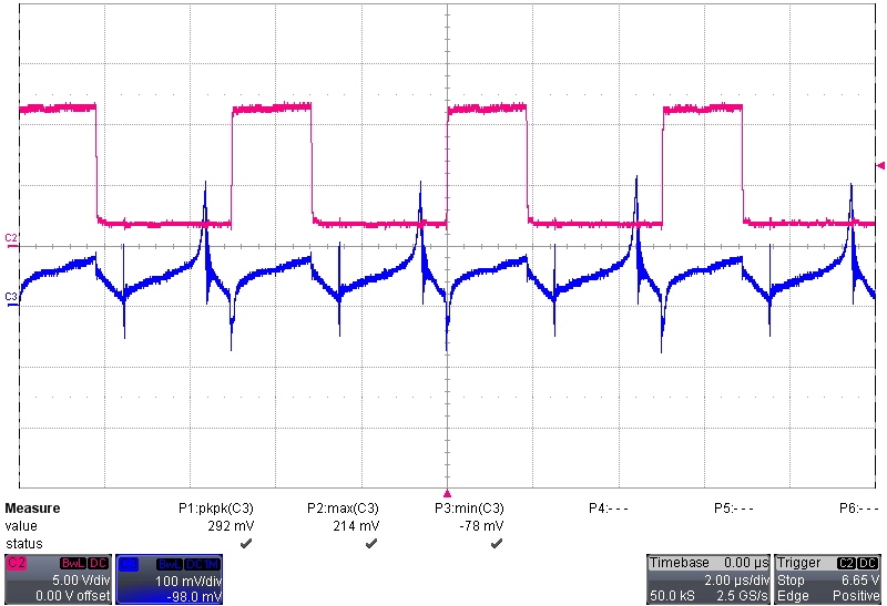
  • Ch2: DPWM0A Ch3: Current signal @EP2

             the control loop is only voltage. you can see the current signal maybe go to saturation status. Then i use the register of cycle adjust to add 10ns duty for calibrate the current signal . It change normal but 10ns is too small . So the voltage loop control is not good for our module. 

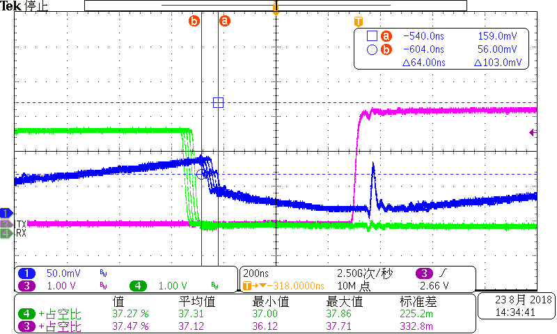
  • Ch1: Current signal @ EP2 ch3: DPWM0A Ch4:DPWM1A

    I get the wave in PCM mode. Although you said that the shake is 50ns, it is ok . but the output riapple will out of the spec. And it have some anomalous concussion. It case the output riapple to became more bad. we want to search the reason, so do some test. By this time, do not know the shake come from voltage loop or current loop.

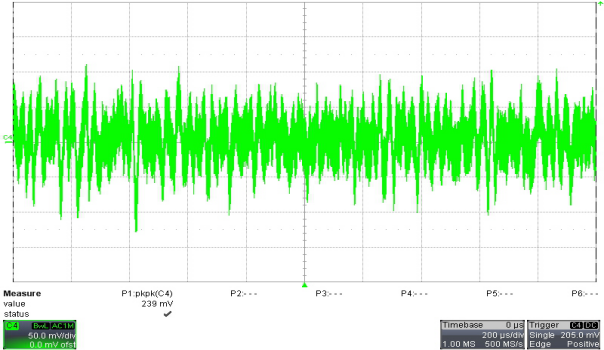
  • The wave is output riapple. The module output voltage is 12V.

  • As I have said before, the output ripple generally doesn't come from a specific loop. It either comes from jitter, from noise in the input signal, or from a mismatch between the coefficients and the power supply plant. I've taken you as far as I can, I'm going to assign this thread to someone who is more expert on noise and coefficients.
  • Hello, Zhiwei,

    Have you checked the loop response? If the bandwidth is too large, the jitter could cause more ripple.

    Regards,
    Sean
  • Ok. Thank you very much!