This thread has been locked.

If you have a related question, please click the "Ask a related question" button in the top right corner. The newly created question will be automatically linked to this question.

UCD9244: Consistent Problem with VOut with UCD9244

Part Number: UCD9244
Other Parts Discussed in Thread: UCD74120, UCD9090

We have built 6 boards based on UCD9244.

One board will not come up. It is putting out minimum duty cycle out of the DPW pins.

No fault signals appear to be present. no overcurrent condition exists.

not sure what to look for anymore.

Replaced the controller once already.

  • Hi Howard,

    We will get back to you on Monday.

    Regards,
    Weidong
  • I'll be looking for it.

  • Is the pulse width about equal between the DPWM pin and its associated switchnode (before and after the driver), i.e. is the driver truncating the pulse?

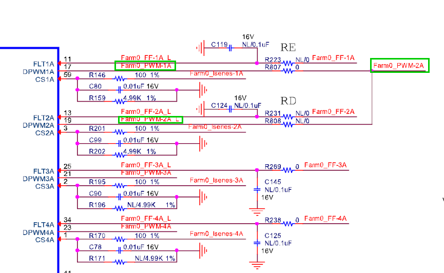
    Can you forward your schematic for the power system and the configuration file for the UCD9244?

  • I will get back to you on this
  • I sent the eval. module - we are almost identical. We have 5 working boards and this 6th one will not come up. Replaced the UDC9244 twice.
    the driver is not truncating the pulse. The width of the DPWM1A pulse is 40-50 nanoseconds with a period of about 1.3 micro-second. The width of the DPWM2A pulse is 30 nanoseconds. The CS1A signal is .5V. The CS2A signal is .5 V with a small amount of ripple. I don't see any ripple on CS1A. I am looking before the filter (right side of R146 and R201. I checked both sides though.
  • The DPWM3A and 4A signals are 0. 1 and 22 read .5 volts, - very low. Would 3 and 4 failure prevent 1 and 2 from coming up? - see schematic. I am working on sending you the config. file.
  • I will attach the config file. I had to add a .txt extension to get it to be read by your site.DSP-1607_Rev2_12V_20180705.tifsp.txt

  • I suspect that both R807 and R808 are populated on the board having the issue, can you confirm?

  • The PWM output is 1/3 the width of a board that is working.

    It NEVER tries to get wider.

    Why would it stay at minimum pulse width????

    I don't see any fault signals?

  • I see now, the two UCD74120 are driven in parallel as a single rail with R808 not populated, the fault flags from both power stages are OR'd together and DPWM-1A is driving the PWM inputs of both power stages. So your configuration file is set up with a dummy rail2 in order to maintain the proper alignment for the rails connected to DPWM-3A and -4A.

    So when you indicted that DPWM-2A was pulsing about 30ns were you referring to the dummy rails DPWM-2A output or the signal jumpered from DPWM-1A to drive the 2nd power stage, Farm0_PWM-2A?

    If you are not using Rail#2, I would disable it by setting the ON/OFF_CONFIG command for Rail#2 to OPERATION_Only, the controller will power up with the OPERATION command set to Off and none of the other rails are defined to use the OPERATION command.

    Just to confirm, the short pulsing starts when the rail is enabled by the Control pin and just continues indefinitely with short pulses, because the rails will normally start at with 20ns pulses but should ramp up from there in several ms time (RISE_TIME is set to 5ms). And there are no fault conditions being reported.

    Have you tried removing the UCD74120 power stages to see if the PWM pulse width increases?
    Given that you have 5 working boards I think we can most likely eliminate the board design and the configuration file for the UCD9244.
    And having replaced the UCD9244, it isn't that.
    And you confirmed that DPWM-1A and DPWM-2A outputs are not tied together by resistor R808.
    There isn't much left other than the UCD74120s, is it possible one of them isn't mounted down correctly and is causing the issue?

    One other possibility, the feedback pins for Rail#1 aren't being back driven from CPU by a higher voltage on CVDD by chance? Incorrect power sequence order controlled by the UCD9090.

    Another thing I just noticed, the OC_FAULT_LIMIT is set to 0A, I've never tried this.
    I do know that if the FAST_OC_FAULT_LIMIT is set to 0A then that function is disabled but I'm not sure if that also applies to the regular OC _Fault_Limit as they are handled in different ways. But it would be set that way on all your boards, so again, if you have 5 working boards it likely isn't this.

    Something else to look at, prior to enabling the rail, DPWM-1A should be in a HI- Z state and a resistor divider in power stage will hold the voltage on the DPWM-1A pin to ~1.65V. The divider is two 50K ohm resistors between BP3(3.3V) and GND.
  • Still won’t come up. I tried removing 0 ohm resistor between FARM0_PWM_1A and FARM0_PWM-2A and inductor from 2nd UCD74120 output – but then I get a fault signal.

    The pwm signal was monitored at the PWM chip (FARM0_PWM_1A  and the USD74120 regulator SW outputs .

    But why would the PWM chip have a low duty cycle if the signal is small?

  • We have replaced the UCD9244 twice and one of the UCD74120's twice (the one with FAM0_FF_1A signal coming from its IMON.

    We don't get any fault signals at all.

  • I can now give the following measurements that I have taken on this board.

    DPWM1A output is 0 to 4V . 60nseconds on 1300nseconds off.

    The UCD74120's SW output is 0 to 14V, 50-60 nseconds on, 1300 nseconds off.

    Filtered output (after inductors, etc) is .500 mV (supposed to be 1.0V). for BOTH UCD74120 devices.

    EAp1 = 500mV, Ean1 = 0V.

    Eap2 = 500 mV, Ean2 = 0.

    Temp 1 = Temp2 = .9V

    Temp3 = Temp4 = .7V

    POWER GOOD = 0V. But I have no idea what this really means other than something is wrong.

    UCD74120 number 1 ILIM = 1.2V, RDLY = .74V, CSP=CSN = .54V

    UCD74120 number 2 ILIM = 1.2V, RDLY = .6V   not sure what the difference means.   CSP=CSN = .54V

  • I had been going over your latest findings yesterday trying to come up with an explanation.

    The fact that the output appears to be exactly half the desired value is a bit suspicious.

    Does the reported voltage in the GUI Monitor (READ_VOUT) return 0.500V or 1.000V when the rail is on?

    The only configuration items that could cause this would affect all the boards if the same file is used to load all the devices.

    There are configuration settings that could cause this but none of them are indicated by the configuration file that was provided: 

    1) Given that there is no resistor divider on the feedback then the VOUT_SCALE_LOOP/_MONITOR configuration values should be set to 1.000, if they were set to 2.000 (which appears possible in the GUI though I've never tried as this would indicate that there was a gain between the PS output and the EA pins) then the output would operate at 0.500V and the GUI would report 0.500V (not indicated by the configuration file provided).

    2)  If there was a feedback resistor divider with equal values of resistors and the VOUT_SCALE_LOOP/_MONITOR configuration values were set correctly to 0.500 but the lower resistor was missing or not making connection (not indicated by the configuration file provided).

    3)  If there was a feedback resistor divider with equal values of resistors and the VOUT_SCALE_LOOP/_MONITOR configuration values were set incorrectly to 1.000 (this would work with the configuration file provided).  But this would require this board to be different from the others and not match the schematic provided.

  • You could also perform a configuration file compare between one of the good boards and the file being used on the board with the issue.

    It is called Project File Compare Tool, in WIN7 and earlier its under the Start menu as Texas Instruments --> Fusion Digital Power Designer --> Tools --> Project File Compare Tool .  If you have WIN10 (at least on my machine) then Microsoft flattens the file structure under any folder below the top level of Start (you're welcome) so that now everything and anything that used the Texas Instruments folder is now jumbled directly under it, so it would be just Texas Instruments  -->  Project File Compare Tool

    You would "Add Project File" to load the file that is being used on the board with the issue then connect through the USB-to-GPIO adapter to the live working board and click the "Add attached devices (offline or online)" which is not highlighted here because I don't have a board connected right now.  Clicking the "Only show differences" box will give you any differences between the two configurations (differences will be highlighted while common items are not if displaying the entire list).  Anything in the Status section is not pertinent as many of these would be expected to be different.

  • We are working on it. Will let you know.

  • Hi Howard,

    Not sure if the issue has been solve.
    Please submit a post if you need further support.

    Thanks
    Qian