This thread has been locked.

If you have a related question, please click the "Ask a related question" button in the top right corner. The newly created question will be automatically linked to this question.

REF5040: RF radiated immunity tests.

Part Number: REF5040

Hi there,

We are currently using this IC as a reference voltage for a ADC.

The problem is that while passing the circuit through RF radiated immunity tests the output pin is not stable and we are getting erroneous ADC readings.

This occurs at 450 to 700 Mhz band.

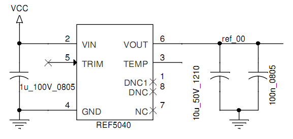
Circuit:

Note that the TRIM pin is open, can this be the cause of this problem?

Regards,

Daniel

  • Hi Daniel,

    Can you give us more information on your setup and results?

    I would add a smaller capacitor in the input/output in the order of 50pF-100pF to decouple RF signal because the 1uF might not be sufficient. I have also seen examples where 2 smaller RF decoupling capacitors (i.e. 10pF + 33pF) are used in parallel to reduce the effect of RF signals. The values depend on the RF frequency needed to attenuate.

    A capacitor in the TRIM pin typically adds a lower frequency pole but it won't hurt to also protect this input.

    -Marcoo

  • Hi Daniel,

    don't you have any shielding for the PCB? This would be the easiest way to solve your problem.

    Take care, when using two or more unequal caps in parallel for decoupling purpose. This can result in huge and sharp impedance maxima, where the caps totally lose their decoupling ability. This especially happens if all the caps are ceramics with very low ESR. In the good old days, when tantals or electrolytics were used in parallel with a ceramic cap, the high ESR of the tantal or aluminium electrolytic damped this resonance. But with only ceramic caps all showing very low ESR these resonances aren't damped at all and huge and sharp impedance maxima can be observed.

    If you really need bigger capacitances, put only identical ceramic caps in parallel. Then resonances will hardly occur. The paralleling of unequal caps makes only sense if one of them has a huge package with huge equivalent series inductance and if you want to shunt it with the lower inductance of a cap with much smaller package. As example: 100µF aluminium electrolytic paralleled by 100n ceramic. But paralleling unequal caps all with the same package (0805 e.g.) makes no sense at all, because there's no big inductance to be shunted by a lower one. You only end up with impedance resonances ruining the decoupling ability.

    Remember: Important for proper decoupling is high capacitance in combination with as low as possible equivalent series inductance. So, take a ceramic cap with as much capacitance as possible in an as small as possible package. in your case this could be a 10µ/0805/X7R cap. Or put two 4µ7/0805/X7R caps in parallel. But don't parallel a 1210 ceramic cap with a 0805 ceramic cap.

    Sometimes, if we need to parallel a transzorb with a ceramic cap or if we need to parallel unequal ceramic caps, we put a small resistance of 0R22...0R47 in series to the ceramic cap. This will dampen the resonance a bit.

    Kai