This thread has been locked.

If you have a related question, please click the "Ask a related question" button in the top right corner. The newly created question will be automatically linked to this question.

REF200: How to design current mirror in PCB to bias current into test chip.

Part Number: REF200
Other Parts Discussed in Thread: OPA602, TL431

Hello everyone,

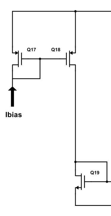
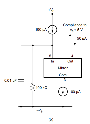
 I have a test chip where I need to give a  50uA dc current into a PMOS drain terminal as it is apart of biasing circuit of a opamp. Power supply level for this chip is 5 V. Now, is it possible to design any current mirror or current sink circuit in PCB level with ref200 model.

  • Hi Heavn,

    must the current flow into the chip, as shown in the picture, or out of the chip?

    Kai
  • I am sorry, the arrow in the figure does not signify the direction. It only implies the connection to offchip current reference. So, the current is coming out from the chip.
  • Hi heavn007,

    It is possible to use the REF200 for this application. Figure 20 on the REF200 DS shows 50uA examples and any of those should work.

    -Marcoo Z
  • Hi Marcoo 

    Thank you very much for resolving this matter. I successfully designed the circuit in PCB (picture is given below) and I measured with ammeter which showed that 50 uA current is coming out from the test IC. I want to know how could I get  40 uA  current sinking out for the same design.

  • Hi Heavn007,

    I am glad to hear that you got your 50 uA current source working.
    One of the advantages of the REF200 is being able to create 50/100/200/300 uA current sources easily and accurately.
    The drawback is that if you want to create a adjustable current source, there is the need for external components.
    Figure 25b shows a current sink schematic using the REF200 and the OPA602 where the current can be adjusted by using external resistors. If you want to continue to use the REF200 then this would be the easiest way to create a 40uA source.

    Another alternative would be to use a shunt voltage reference such as the TL431. on the TL431 datasheet, figure 39 shows a popular implementation of a current sink. This solution is simple and can create a 40uA current sink. Due to the flexibility of the current sink, the TL431 can be substituted for even higher precision shunt voltage references. Depending on your accuracy and temp co needs, there is other alternatives that can offer more precision at a higher cost in complexity.

    -Marcoo Z