This thread has been locked.

If you have a related question, please click the "Ask a related question" button in the top right corner. The newly created question will be automatically linked to this question.

REF102: REF102

Part Number: REF102
Other Parts Discussed in Thread: OPA277, REF5050, LM4140, LM4132, LM4040, LM334, LM4040-N, LM234, INA121, INA114

Hi 

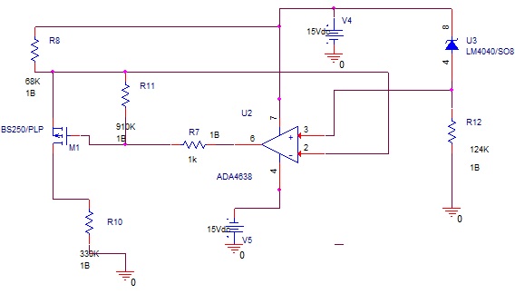
I need to design a current source of about 30 micro amps (UA) 

it should be totaly stable max 0.1 % error

The 30 UA can be changed between 28 and 40 ua if better but the stability must be sure

The aim is to measure loads resistors which vary from 100K to 400 K

THe ps available are + and - 15V

I"ve found the application note with ref102 and a OPA111 wich shoul be a solution

But I must design with CMS components and OPA111 doesn't exits?

Which module should I use ? OPA277 or ?? 

Thanks a lot for your support

  • Hi Claverie,

    I have looked into the application note that you reference and it is valid. The OPA111 is not recommended for new designs but the purpose of that amplifier is to isolate the ground current from the current source to provide a more accurate voltage reference. This basic configuration is very flexible and applicable for all voltage references. The same can be true for the amplifier for the OPA111. I do not see any obvious issues with using the OPA277.

    For example the LM4132 has a simplified current source configuration in the datasheet on pg 9. You can use the LM4140 or other devices such as the REF5050 for this.

    -Marcoo
  • Hi
    First Thank you for your quick answer !
    Just some details ?
    When you told about pg 9 for the LM4132 .. is it the fig 53 in its datasheet ? (a programmable current source ?)
    If yes.. I don't understand how I ca assume the value of IGND of the module and so the statbility of the current in the load ?

    for LM4140 and REF5050 withc are voltage references .. do you thnik about using them alone or in addition of an opa277 or other as I 've found application as I was telling in my 1rst post ?

    do you know application examples for my current source I need ?
    Thanks again for your support

    Regards
  • Hi Claverie,

    For the LM4132, figure 53 shows the programmable current source but if you can make it a fixed current source by eliminating Rset. The IGND is the current the device needs to function. This value is typically close to but greater than its quiescent current when the device has a load. This current will need to be taken into account in order to get the accuracy you require or it will have to be eliminated by using a amplifier in the configuration in the app note you viewed.

    Both the LM4140 and REF5050 devices will work in the configuration from figure 53 but if your current source is going to be 30uA then I would highly recommend a opa277 because the IGND will dominate the output current. My concern with these devices is the stability of the devices due to their CLoad conflicting with the OPA277 Cload.

    I am not sure how many boards you are making but to reach 0.1% accuracy you will need even more accurate resistors and calibration because the resistor errors, voltage reference initial accuracy, temperature coefficient errors will push the boundary of 0.1% without proper calibration.

    -Marcoo
  • Hi and thanks again

    Juste a precision 

    I think my approximate english has created a non understand

    When I speak about 0.1 % its not the precision of the source (I can have in my application a fixed value beside 25-35 UA)

    But when the value is set IT MUST NOT get more tnat 01% of variation 

    The aim is to measure resistors . I will calibrate the value of the current and my measurement chain ( an DVM card)

    But after the value of the current source MUST be stable 

    I've already test another solution and from 30UA when I change the load resistor the curent varie about 3 uA regarding the charge of the current source

    It's not suffisant for me in terms of value of resistor I must test

    Perhaps I get au probleme on my Operational amplifier (ADA4638) or the MOS (BSS250) 

    M reference source was a LM4040 2.5V

    Thanks

  • Hi Claverie,

    From my understanding, you are performing calibration on the units to get rid of DC errors such as initial accuracy. In this situation then the only errors that can affect your system will be temperature coefficient. If you calibrate your system at the temperature you will using the device in, then you can ignore temperature coefficient if the ambient temperature does not fluctuate.

    Can you share the schematic for this current configuration?

    Because you are doing calibration, I can recommend the LM334. The initial accuracy error is greater than your error budget but with calibration then you should have no problem using it. I think this is a better solution since it is built for being a current source.

    -Marcoo
  • Hi Marcoo

    Here after you"ll find an simulation I ve done for my current source

    The lm4040 is a 2.5 V model

    Dont matter about value of R8 which fix the current. I've adapted it on test to have about 30 uA

    the resistor to be measured is of course R10

    It's value will be between 100 K and 400 K

    In simulation It 's ok but on test the current varie from 30 UA to 33 UA directly linked to the value of the resistoir to be tested

    Il's why I speak about stability .. 3 UA of error is to musch for having precision in measure of the resistor

    Thanks

  • Hi Claverie,

    Thank you for the schematic. In your implementation you have a lot of passives to adjust and you are using a FET for high current even though only low current is needed. Have you tried implementing figure 16 or 17 from the LM4040-N datasheet? You have the right components for this schematic. Sadly all non ideal current sources do have some variance and its hard to simulate the issue.
    www.ti.com/.../lm4040-n-q1.pdf

    -Marcoo
  • thanks a lot marco
    I'm going to test your proposed solution
    I'll keep you informed
    Regards
  • Hi

    I've simulated the solution that you've proposed with LM4040 (fig17)

    I don't succeed to find the right résistors for my application et the design is ot working

    See here after the current in the load is not VOUT/R2 as told in documentation

    I've succed to have the right value of curent by changing résistors values but ILOAD is changing between a 100K and 300K load resistor ???

    I've tried to respect the datasheet which told us to have current in the LM4040 higer than load but

    probably I 've not well understood  ???

  • Hi Claverie,

    In your schematic, either the Vdd needs to be higher or the value of R13 needs to be higher to limit the current because the device is running into headroom issue. If you increase R13 to 83k Ohms then you will have a current around 30 uA.

    -Marcoo
  • Hi Marcoo

    Sorry for the delay I have to order component 

    I've tested the uppon schematic and it's OK 

    More I 'm looking for using more simple schematic and I've found the LM234 which seems we can use alone with only a resistor 

    for my application

    Do you think it's possible 

    regards

  • Hi Claverie,

    I am glad to hear that you have something working. The LM234 works for your purposes. The only reason I did not recommend it right away is because the device does vary heavily with temperature more than a series + op amp combination. If you are using this device in a temperature environment that does not vary much, then this device will be the simplest solution.

    -Marcoo
  •  

    Hi and thanks Marcoo


    The solution seems to be stable

    I try now to implement thant on my original measurement chain on the original

    The input chain is the schematic above


    As you see my resistor to be tested supplied by the current source is on the left of the schematic

    you can easily imagine I get the problem that the impedance input of the chain is too low compare to the 300K resistor I must measure

    So il Think about replace this input stage by an INA114 or INA121 with gain of 1

    But I don(t see the difference between these 2 modules and not sure it' s the right solution

    I think you are perhaps not the specialist of the AO but coul you give me information wehre to post this if needed

    Regards and again many thanks for your support

    Alain

  • Hi Alain,

    To get more in depth differences, try the amplifier sub-forum. They will be able to point the relevant differences between the devices. If you have any more questions regarding voltage references, feel free to reach out to this sub-forum.
    e2e.ti.com/.../

    -Marcoo
  • hi Marcoo
    thanks a lot
    I mark this message as resolved
    regards